buzzforb. Are you interested in a procedure to turn on your balanced diyF6 for the first time?ah! more pics soon. I may try to fire it up after all. Gotta get some other stuff done. Just depends on the progress.
@flo
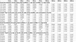
1u is way too much
been there , erred almost the same
Where is the rest of the table
 and what was the calculation. Way too busy and lazy to look for myself. Are we talking snubbbers here, or just bypass caps? I have heard some folks dont like snubbers, whats your opinion. Gotta go finish tapping sinks. I hate tapping, even with drill.
buzzforb. This is a suggested procedure. Your pcb shows that power to both amps is applied simultaneously.Where is the rest of the table
- Separate the turn-on of the amps
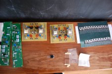
- Cut with razor the +Vc and -Vc traces to left channel. Ideally, each channel may have had its +/-Vc lines independent from the other.
- Ground the bridge resistor; the one [low value] connected to the primary winding of the Left Amp. Is this 18 Ohms? I only see one resistor bridging R and L amps.
- Bias this R amp l like you've done with diyF6 .
- Disable power to the R amp [razor cut the traces].
- Lift the feedback resistor off ground.Connect its other side to ground.
- Repeat the above for the L amp tyo bias the left amp.
- Disable power.
- Lift the bridge resistor off ground.
- Now you are ready to apply power to both amps.
buzzforb. This is a suggested procedure. Your pcb shows that power to both amps is applied simultaneously.
- Separate the turn-on of the amps
- Cut with razor the +Vc and -Vc traces to left channel. Ideally, each channel may have had its +/-Vc lines independent from the other.
- Ground the bridge resistor; the one [low value] connected to the primary winding of the Left Amp. Is this 18 Ohms? I only see one resistor bridging R and L amps.
- Bias this R amp l like you've done with diyF6 .
- Disable power to the R amp [razor cut the traces].
- Lift the feedback resistor off ground.Connect its other side to ground.
- Repeat the above for the L amp tyo bias the left amp.
- Disable power.
- Lift the bridge resistor off ground.
- Now you are ready to apply power to both amps.
buzzforb. Here is a much simpler procedure [than above] to start up.
- Cut with razor blade the traces emanating from the outputs to the 100 Ohm feedback resistor of each amp.
- Thus, both amps are no longer bridged, and each operates open loop, and independently for biasing..
- Apply power. Adjust the bias and stabilize the operating point of each amp like in diyF6 [one hour].
- Preheat the soldering iron
- Turn power off to the balanced diy amp
- Give yourself one minute to solder the traces that you cut.
- Power up.
Best regards.
You are welcome. Hate to see inadvertent problems in your work. The simpler procedure above is also useful to start up a solo diy F6. First there is no reason to subject the feedback resistors to a +/- output voltage, and more importantly to push a Direct Current through the primary; a no no per JensenOk. Thanks. Probably will not get to it today.
You are welcome. Hate to see inadvertent problems in your work. The simpler procedure above is also useful to start up a solo diy F6. First there is no reason to subject the feedback resistors to a +/- output voltage, and more importantly to push a Direct Current through the primary; a no no per Jensen
Can't say I understand this. The offside transformer will not be connected to ground. How can dc flow through it. The series feedback resistor will function as it normally would in standard F6.
Can't say I understand this. The offside transformer will not be connected to ground. How can dc flow through it. The series feedback resistor will function as it normally would in standard F6.
I am proposing that a current will flow through the primary winding from the grounded feedback resistor [ say 1 VDC ], then through the sources of the FE JFETs and out of the drain of the p-channel JFET [grounded common gates] so as to absorb their new current imbalance.
I am surprised that you connected Zen pots. Your bridge amp is expected to have lower distortion [due to distortion cancellation] than either of its solo diyF6s which already have low distortion before and after loop feedback. Afterall, are'nt you aiming at a vanishing distortion with your bridging setup; maybe in the range of 0.001% -0.0001% THD. Maybe the pots are for bias. In this case please strike off my comment.
Last edited:
Zen Mod. Homework is a bitter pill, and is fortunately therapeutic. I already have four R100As, and their PCBs from Tea-Bag. I am also waiting for a diyF6 kit [parts inclusive backup output MOSFETs] from buzzforb's past GB; forthcoming in a month. PSU is forthcoming also.Antoinel
when we are going to see your homework ?
( just ignore fact that nobody can see mine , that's the way the things are )
I have other 'skunkworks' projects on semi-standby, as I simultaneously attend to this thread.
There is a probability that a solo diyF6 in your setup is connected to have a closed loop gain equal to 1. Potential for oscillation!I am not looking for vanishing distortion. I have not hooked up zen pots. The two sides will not be connected. I will bias each side separately.

- Home
- Amplifiers
- Pass Labs
- F6 Amplifier