just that one
search and you'll see it , too

edit : I presume all slides will be in article
but , I understand Papa - we are (mostly) annoyin' PITA

(edit: search for posts of guy having Neumann-like ears , and liking ГУ50 plugs
") )
)
Last edited:
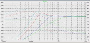
I did a simulation of that circuit and got about the same results as with my Teaser-6 circuit. I question the choice of 470uf-1000uf for the bias coupling caps. In the simulations there is only 30 degrees phase margin at .06Hz. In the actual Teaser-6 builds with 470uf caps, the noise floor and harmonics were seen to "bounce around" significantly at a frequency of about .1-.2 Hz. When I reduced the caps to 100uf, this problem went away; verified by both the simulations and the actual builds.
In the plot, the colors are as follows: blue=100uf, red=470uf, and blue=1000uf.
In the plot, the colors are as follows: blue=100uf, red=470uf, and blue=1000uf.
you can make this one in a meantime
disclaimer - from slide 13 of 19
really don't know what was in later slides
Papa still didn't sent me lecture and I doubt it will

Attachments
I'm used to trust in Pa's simple solutions
in those cases , simple means elegant .
even if you can get better results , when circuit is intended for Greedy Boyz , Pa is not going to squeeze last ounce of performance , from simple reason - not every greedy boy is having THD measuring facility
one who is having that - is free to fire up both his brain and measuring equipment
whatever - if your amp is , in any way , in situation to worry about 0.1 or 0.2 Hz , you're in trouble
there is no way that you can find it in motorboating region
edit : how you measured that behavior in vivo ?
Last edited:
How can a reduction of the values of the bias caps be considered an increase in the circuit complexity?
I used two separate measurement systems which both gave similar results. The first was Visual Analyzer Visual Analyser 2011 XE, running continuously showing the spectrum for a 1 watt sine signal at 1kHz, updating at about once per second. The second measurement system was my own software, which is similar to Visual Analyzer, also running continuously showing the spectrum with frequent updates. With both measurement systems the noise floor and strength of the harmonics bounced around significantly with 470uf caps. When the caps were reduced to 100uf that problem went away. The problem did not manifest itself as audible motorboating, but I suspect that careful listening would detect it as temporal variations in the levels of the harmonics. In an early Teaser-6 build, with a different bias circuit, I was able to stimulate it into runaway motorboating at a frequency below 1Hz.
I used two separate measurement systems which both gave similar results. The first was Visual Analyzer Visual Analyser 2011 XE, running continuously showing the spectrum for a 1 watt sine signal at 1kHz, updating at about once per second. The second measurement system was my own software, which is similar to Visual Analyzer, also running continuously showing the spectrum with frequent updates. With both measurement systems the noise floor and strength of the harmonics bounced around significantly with 470uf caps. When the caps were reduced to 100uf that problem went away. The problem did not manifest itself as audible motorboating, but I suspect that careful listening would detect it as temporal variations in the levels of the harmonics. In an early Teaser-6 build, with a different bias circuit, I was able to stimulate it into runaway motorboating at a frequency below 1Hz.
I'm used to trust in Pa's simple solutions
in those cases , simple means elegant .
even if you can get better results , when circuit is intended for Greedy Boyz , Pa is not going to squeeze last ounce of performance , from simple reason - not every greedy boy is having THD measuring facility
one who is having that - is free to fire up both his brain and measuring equipment
whatever - if your amp is , in any way , in situation to worry about 0.1 or 0.2 Hz , you're in trouble
there is no way that you can find it in motorboating region
edit : how you measured that behavior in vivo ?
remark about simplicity was general , not exactly connected with your question
whatever , what I meant with that is that I'm usually respecting his choices
even if I'm notorious in using everything shunt regulated , while he is not
however , it's best to ask him about those small details , when you see exact schm and article
whatever , what I meant with that is that I'm usually respecting his choices
even if I'm notorious in using everything shunt regulated , while he is not
however , it's best to ask him about those small details , when you see exact schm and article
Correction: green=33uf, blue=100uf, red=470uf, and cyan=1000uf.
...
In the plot, the colors are as follows: blue=100uf, red=470uf, and blue=1000uf.
(edit: search for posts of guy having Neumann-like ears , and liking ГУ50 plugs
man ZM you really are one resourceful guy
... amazing !!ya know what's written in biggest Patent Book in history :
Ask, and it shall be given to you; seek, and ye shall find; knock, and it shall be opened to you
lookie
Ask, and it shall be given to you; seek, and ye shall find; knock, and it shall be opened to you
lookie
An externally hosted image should be here but it was not working when we last tested it.
Attachments
Last edited:
you can hear speaking Nelson over an hour about F6 ........
http://www.diyaudio.com/forums/pass-labs/222272-burning-amp-tweets-10.html#post3222773
by courtesy of Mike R. and his helpers here...
thanks so much Mike!
http://www.diyaudio.com/forums/pass-labs/222272-burning-amp-tweets-10.html#post3222773
by courtesy of Mike R. and his helpers here...
thanks so much Mike!
ask Tea for leftovers
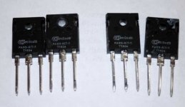
whatever - every proper Greedy Boy must have at least 2 pairs in drawer ....... or in amp
Moi got 8
Attachments
4.50$
Please this is a serious offer....!

- Home
- Amplifiers
- Pass Labs
- F6 Amplifier