you asked .....
Interesting.. But would this work in practice ? Here are some issues:
I think based on my own past experience that the coyote and rOadrunner are out of phase...
Secondly, there is the issue of wind resistance and variability caused by fluctuating atmospherics interfering with the otherwise parabolic descent of the payload
Nonetheless interesting idea ..... I'm sure the more experienced ones can add further

 I'm a hound dog, not a bird dog
 Ya, ya, ya, I don't know myself but, based on Papa not making a mistake in the o and o . I beleive there is a posibility the wrong phase/gain device is helping distortion and the easy to understand 1/2 of the circuit might be more normal to understand. I obviously don'nt quite get it yet.
Previously I stated "it might take a few beers". Last night I had a few Martini's
instead? but I beleive the device providing the wrong polarity feedback is providing a more local control of the other 1/2s non linearity... ???
I've yet to sim this thing. that alows free'er thinking and easy experimenting but, I have a little trouble with a Xfrm'r sim without just playin until it works??? This weekend maybe...
My simplististic mental picture of the in-phase drive in F6 follows. The channels of both JFETS will open wider when they simultaneously receive an equal positive signal drive. A current larger than standby will rush between +Vc to -Vc. Will some of this added signal current be diverted to the load [and then to its ground], and not bypassed fully to -Vc? Yes, only if the bottom channel is less open than the upper one due to this unique output topology. So, the bottom choked JFET is a high impedance to the upper JFET which is working in the common drain configuration. On the negative stroke, both channels will be choked. Are they choked equally? It cannot be yes. Current flows from ground through the load and then through the bottom channel if it is substantially more open than the upper one. Thus, the upper choked JFET is a high impedance load to the bottom JFET working in the common source configuration. This is a power amplifier. How's the topology manage this selective opening and choking of the channels to do useful work in a loudspeaker?
...... How's the topology manage this selective opening and choking of the channels to do useful work in a loudspeaker?
I still think we need to wait , to see what's Papa's next tip ;
it's either push pull (misplaced little circle in schmtc), or wakoo SE ;
it's easy to control amplitude of upper modulation
be sure that he tried all those mysterious ways ........ and chose,for him, most amusing one
OK really noobish attempt to understand this.
From what I can understand with my (again noobish) knowledge, the top and down mosfets are cancelling/balancing each other.
The difference making things work comes from the resistor divider that goes below the transformer to the top source breaking the balance?
So the top mosfet works from the voltage from the secondaries plus the remaining from the primary, while the bottom only with that of the secondary?
Hi All,
I'm sorry to ask what must be a dumb question but I've been waiting for someone to mention it and if they did I missed it somehow.
What is the 'V' in a circle that is attached to the transformer secondaries? In my spice centric brain that means a voltage source but I suspect that's not the case here.
Anyway, I've been enjoying all the discussions. Can't wait to see a working schematic.
Attachments
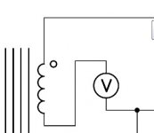
DC voltage source , conveniently placed there , to properly bias output Jfet
Thanks ZM, how would you invision it being implemented? A battery, or would you need actual psu? There would be virtually no current required correct?
I have a phono pre-amp that uses a small 1.5v battery in series with the input signal to bias the grid of the 1st vacuum tube. No current needed so battery lasts for years.
Attachments
line splitter cinemag......
Audio Splitter Transformers
Dear Gerd;
Thank you for your inquiry about the CMOL-4x600T2. They are $163.79 each. This is an expensive transformer originally designed for feeding satellite trucks and venue recording consoles at the Academy Awards, which gives you an idea of its application. Tell me about your application if you wish so that I might help you figure out the best transformer. If you only need two of them, Priority Mail Flat Rate will be $16.95. Express Mail will be $41.85. We manufacture to order, so the lead time will be a few weeks.
Best regards,
David Geren
Probably a custom order with any transformer company. maybe a group buy with one would reduce the price.
Last edited:
O.K. here comes my second search, I asked Edcor for a suitable device...
"You can check out the XS4400 on our website. It is 1:1:1:1 for line level signals
Phyllis Weston"
EDCOR - XS4400
"You can check out the XS4400 on our website. It is 1:1:1:1 for line level signals
Phyllis Weston"
EDCOR - XS4400
You can check out the XS4400 on our website
That's not expensive enough for high-end audio!
It is also possible to use 2 transformers with 1:1 windings. You'll see.
primaries paraleled in phase
secondaries in , ahem , (anti)phase
Attachments
OK keeping my noobishness incoming, so feel free to slap me if I don t make any sense.... the separate voltage sources could be a nice indication too...
The bottom mosfet is in common source, so inverting (which indicates rather push-pull if the transformer Os are correct).
If its voltage source is high enough, its current could be driven by its drain voltage, so the output of the top mosfet? The slope would be different though, since the bottom would be driven by its drain and gate.
Maybe this is why only the top one gives feedback?

......
Maybe this is why only the top one gives feedback?
why you think that ?
observe amp as black box , with input , output and NFB between these two nodes (around black box)
how then just one half can give NFB ?
between these two nodes you have one mechanismus , while NFB loop is holding it's b00l$ in tight squeeze
- Home
- Amplifiers
- Pass Labs
- F6 Amplifier