Hello,
Here is also one approach")
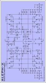
The picture is too big to upload, and this smaller below is little fuzzy.
This is the link to the full size : http://web.vip.hr/pcb-design.vip/aleph-x.html
Hopeing to build this as my next DIY audio project
Here is also one approach
The picture is too big to upload, and this smaller below is little fuzzy.
This is the link to the full size : http://web.vip.hr/pcb-design.vip/aleph-x.html
Hopeing to build this as my next DIY audio project
An externally hosted image should be here but it was not working when we last tested it.
Re: Output resistors
gain of the current source.
The ratios are arbitrary, but you might have to adjust the currentMikeW said:Shouldn't the twice as many output resistors as sourse resistors? The Aleph 2 has 1 ohm source resistor and half ohm output resistors.
gain of the current source.
Since you've chosen to cap-decouple the front end from the output, you no longer have to use 392 ohm resistors for the front end load resistors. Given that you seem to be going for power you might consider using a higher value. Particularly if you intend to use the circuit in a bi-amp setup with a different amp that might have a lower power output. The idea being that it would be nice if both amps (the higher powered one and the lower powered one) reached full power about the same time, which will take more gain on the part of the big amp.
Which I'm assuming is this one...
Now, assuming that you intend to use this as a tweeter amp with an X-1000 driving the woofers, ignore the above.
Grey
Which I'm assuming is this one...
Now, assuming that you intend to use this as a tweeter amp with an X-1000 driving the woofers, ignore the above.
Grey
Hello,
Thank you for the response.
Mike, the source resistors are fine, but you can use even 1 Ohm,
but than the amplifier would run at much lower bias.
I plan to use 1000 VA (2x22 V) transformer, and the 0,47 Ohms
seems to be the optimum on the little tight side.
This circuit above normally would require around 1200 VA,
or even better 1500 VA (per channel) if you would like to be on a
very safe side.
'The one and only', thank you for the advice.
I planned to use 16 Ohm speakers with this amplifier, but now I
would probably use ones with 8 Ohms impedance.
John, this layout must have these resistors to function properly.
The overall gain would go little down, but there would also be
much less distortion at the output.
They also serve for the setting the gates of the gain transistors
at the 4 V, together with the 15 K and 10 K trimmer.
It is recommended to use multiturn trimmers, as the setting the
output offset would be far more easier and precise.
ih6you, it is not that strange as it looks at first look.
It should work just fine.
Grey, the 392 resistor would be left in the circuit to safely test the
amplifier, but it could be replaced with the some similar value.
I plan to use this amp together with the Aleph 5 and with the
active crossover.
Best regards,
Kristijan Kljucaric
http://web.vip.hr/pcb-design.vip
If I understand it correctly, this design is pretty bizarre, and utterly un-buildable.
All this current dissipated for a 16 ohm load? Are you sure you want 3 100 ohms resistor in parallel going to -26V and not to ground?
In any case you would be circulating as much current in these resistor as in your speakers.
All this current dissipated for a 16 ohm load? Are you sure you want 3 100 ohms resistor in parallel going to -26V and not to ground?
In any case you would be circulating as much current in these resistor as in your speakers.
Looks very elegant to me.
A few questions: Why do you decouple the front end?
There must be a good reason, as these caps are in the signal path.
Can the protection circuit still be added? (Q4, Q9 in the original AlephX) ? And why the 100ohm resistors to -V? Isn't that a waste of power as Grataku states?
Does this work similar as R1, R4 and R44, R45 in AlephX V1.0?
Nice job nevertheless.
/Hugo
temperature coefficient
This circuit will run into heavy thermal trouble as the active
current source follows the base emitter voltage of its transistor.
This voltage sinks with about 2mV / K and thus the CS has a
negative coefficient.
As the gain powerfets have a positive coefficient of about 2mV / K
and this is nowhere compensated you will have thermal drift
on the output. As NP stated once, you have to listen with a
screwdriver in yout hand and readjust offset every 5 minutes or
so during listening.
Uli
grataku said:If I understand it correctly, this design is pretty bizarre, and utterly un-buildable.
This circuit will run into heavy thermal trouble as the active
current source follows the base emitter voltage of its transistor.
This voltage sinks with about 2mV / K and thus the CS has a
negative coefficient.
As the gain powerfets have a positive coefficient of about 2mV / K
and this is nowhere compensated you will have thermal drift
on the output. As NP stated once, you have to listen with a
screwdriver in yout hand and readjust offset every 5 minutes or
so during listening.
Uli
Re: temperature coefficient
is local and trimmed. I think it won't be that much of a problem,
nothing that matching the two halves won't minimize.
There is, however, DC feedback Zen on each output stage whichuli said:This circuit will run into heavy thermal trouble as the active
current source follows the base emitter voltage of its transistor.
This voltage sinks with about 2mV / K and thus the CS has a
negative coefficient.
is local and trimmed. I think it won't be that much of a problem,
nothing that matching the two halves won't minimize.
Hi Kristijan,
I saw on your site that you have modified your original design for an Aleph-X considerably. This version 2 uses 12 mosfets instead of 24 per channel...
Are you already building a prototype?
Will you offer pcb's when the probing is done?
Good luck, and kindest regards,
Lucas.
I saw on your site that you have modified your original design for an Aleph-X considerably. This version 2 uses 12 mosfets instead of 24 per channel...
Are you already building a prototype?
Will you offer pcb's when the probing is done?
Good luck, and kindest regards,
Lucas.
Attachments
Hello,
Thanks all for the suggestions.
Grataku, 33.3 Ohm resistor that was going to the negative rail, was a drawing
error that occured when I used one existing schematic of the Zen amplifer to
draw Aleph X v2. Now everything is corrected and trimmed, and the three
100 Ohm resistors are now replaced with the 4 x 150 Ohm, just to have slightly
more power rating on them.
Lucas, there are two versions of the Aleph-X.
The 'regular' one (the one that you posted the picture above, located at the :
http://web.vip.hr/pcb-design.vip/alephx.html
and the Aleph X v2 (the one that is posted at the Post #1 of this thread, located at the :
http://web.vip.hr/pcb-design.vip/aleph-x.html
The PCBs are almost finished, and they would be available as soon as I test them.
William, the BC 550 C transistors can be used without any problems.
I used BC 546 B because I already have them, and they have even higher brake
down voltage rating, even this is not that much important here.
David, the power rating of Aleph-X (12 Fets) should be around 100 W / 8 Ohm with the
specified components and power supply voltage.
Also, if desired, it can be builted with other power ratings, with little different bias, power
supply voltages, and number of Fets.
Best regards,
Kristijan Kljucaric
http://web.vip.hr/pcb-design.vip
- Status
- This old topic is closed. If you want to reopen this topic, contact a moderator using the "Report Post" button.
- Home
- Amplifiers
- Pass Labs
- ALEPH-X - The Monster