Given that you are having problems, you would want Fig. 10, assuming that
you are using a depletion mode part.
Also given that you are having problems, perhaps you should insert a 100
ohm or so resistor in series with the Gate of the Mosfet.
The idea that it works with one source and not another is quite suspicious.
Measure some of the DC voltages for us.

you are using a depletion mode part.
Also given that you are having problems, perhaps you should insert a 100
ohm or so resistor in series with the Gate of the Mosfet.
The idea that it works with one source and not another is quite suspicious.
Measure some of the DC voltages for us.
Last edited:
I think I have solved my problems. It was ZenMod who caused some doubt.
Nelson. What I don't understand is :-
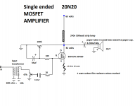
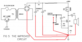
I have built the amp as per Fig 5. This suggests that this is an "improved" version of the first iteration. Fig 10 is an "icing on the cake" working (as far as I can see and suggested that this equals a 300B amp).
Are you saying that unless I build as per Fig 10 I am wasting my time?
I am using 20N FETS. I am pretty sure that the circuit is NOW working correctly. I will measure the DC voltages.
Rob.
Nelson. What I don't understand is :-
I have built the amp as per Fig 5. This suggests that this is an "improved" version of the first iteration. Fig 10 is an "icing on the cake" working (as far as I can see and suggested that this equals a 300B amp).
Are you saying that unless I build as per Fig 10 I am wasting my time?
I am using 20N FETS. I am pretty sure that the circuit is NOW working correctly. I will measure the DC voltages.
Rob.
If the "Improved" example biases up properly, you're good to go.
OK. Will report back in the next few days. Thanks for your help.
Rob.
Ta Da!!! It is done (apart from a very slight mains hum) will increase the PS caps.
Now to tidy and pretty it up.
Now to tidy and pretty it up.
An externally hosted image should be here but it was not working when we last tested it.
An externally hosted image should be here but it was not working when we last tested it.
Put the PS cap banks close to the power amp circuit?
....
conditio sine qua non , besides proper wiring scheme
.....
What about split rail?....
in your case , thats of secondary importance
.....I have all grounds in with -volts?
clarify
Signal grds are attached to pwr grd. It is a single rail supply.
make a point under source resistor your central gnd
keep caps close to main circuit
post close up pics of your wiring when you make as I said , in case that you have some residual hum even then
make a point under source resistor your central gnd
Connecting the RCA (IN) grd in the way you suggest just shorts the input? But the hum stops.
Yes, this is correct.
What you basically have here is a one point grounding of important signal path areas. The hum should be greatly reduced as a result.
By the way, has anyone tried to build my high voltage version yet?
I would be very curious to hear your impressions on the difference between the standard circuit and the modified one. The input transformer really brings this amp to life!
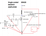
what I meant is this
Are you able to apply the same grounding lines to this?
An externally hosted image should be here but it was not working when we last tested it.
Thank you. I will try it tomorrow. We have the Olympics here
to watch tonight.- Status
- This old topic is closed. If you want to reopen this topic, contact a moderator using the "Report Post" button.
- Home
- Amplifiers
- Pass Labs
- De-Lite strange problem