I am tweaking an F5 Amp and using IXFN 180 n10 and IXTN 170 p10p power MOSFET's.
http://ixdev.ixys.com/DataSheet/98546.pdf
The channel resistance of these is less than 0.012 ohms - that's not a typo.
Have lowered the current detecting resistors R11 and R12 to 0.1 ohm
and changed resistors controlling the current limiting bi polar transistor appropriately.
Have prototyped these MOSFET's in Aleph style amps and the F5 biased at 0.4 amps.
The sound is jaw dropping.
However, these power MOSFET's have 10 times the transconductance of the
power MOSFET's spec'ed for the F5.
Because the transconductance is 10 times, I am concerned about thermal run away,
and do not want to be a member of FAB (N.P. refers to them as Fearless Audio Builders).
So, I either lower the voltage gain of the first stage, or increase the Feedback.
any recommendations ?
Thanks,
Last edited:
I'm not sure about your deduction stream...
You have abundant transconductance but you decide to skimp on degeneration and to increase feedback - both things will endanger stability. If you are OK with 0.4A bias you could increase MOSFETs' degeneration resistors to 1R and increase the gain to 20dB or more.
Also, parasitic capacitance of your MOSFETs are many times higher than usual and it would be wise to double the input JFETs in order to provide enough drive for output MOSFETs. Otherwise the amp's bandwith will be too narrow...
Juma,
Thanks for your response.
I'm not sure what degeneration is.
However, there was a noticeable improvement with the bass,
when the current detecting resistors were decreased from 0.47 to 0.1 ohms.
0.4 A bias was just for prototyping - I'd like to set the final bias at around 1.2 Amps.
But this all depends on ripple on the supply rails.
BTW: I've realized the PSRR of the F5 is the weakness of this amp,
so I've doubled up the all the components of the original power supply.
The parasitic capacitance of the Gamut style MOSFET's is 10 times the value as those transistors spec'ed for the original F5.
However, with these MOSFET's, I don't hear any high frequency roll off.
As I recall, the bandwidth of the F5 is very large.
Some people reduce the bandwidth by adding capacitance to the F.B. loop.
I have tried doubling up Q1 and Q2 to increase the drive current for the power MOSFET's.
The amp becomes a touch more dynamic with the doubling up of Q1 and Q2.
However, this is matter of sonic taste.
So you are suggesting increasing the gain of the amp to about 20 dB's or more, to make it more stable ?
Maybe increase R5, R6, R7 and R8 to 200 ohms each, so that 100 ohms = R5 // R6 ?
Thanks,
Uu, google for "source emitter cathode degeneration" to understand what those 0R47/3W resistors really do. Sensing an Id from them for current limiting is not their primary purpose. Reading and understanding F5 article will help a lot. You want your amp electrically and thermally stable.
High gm output devices give you more OLG so you can have more CLG and still keep the linearity. Generally, more feedback (less CLG) tends to provoke oscillations. F5 is very tolerant about this but don't push it too hard (having a scope to check the amp's behavior with real-life load would be nice). If you want to try changing the feedback ratio you can just unsolder R7 and R8.
F5 is a quiet amp, it has a good PSRR, but doubling the PSU capacitance can be of benefit - just don't use cheap chinese ELKOs, it's a proven method to ruin the sound.
Anyway, experimenting is the way to find the configuration you like. Have fun
Uu, google for "source emitter cathode degeneration" to understand what those 0R47/3W resistors really do. Sensing an Id from them for current limiting is not their primary purpose. Reading and understanding F5 article will help a lot. You want your amp electrically and thermally stable.
High gm output devices give you more OLG so you can have more CLG and still keep the linearity. Generally, more feedback (less CLG) tends to provoke oscillations. F5 is very tolerant about this but don't push it too hard (having a scope to check the amp's behavior with real-life load would be nice). If you want to try changing the feedback ratio you can just unsolder R7 and R8.
F5 is a quiet amp, it has a good PSRR, but doubling the PSU capacitance can be of benefit - just don't use cheap chinese ELKOs, it's a proven method to ruin the sound.
Anyway, experimenting is the way to find the configuration you like. Have fun
Juma,
Thanks for pointing me in the right direction concerning thermal stability.
I went through the original F5 discussion quite thoroughly, and don't recall degeneration being discussed.
I thought the 0.47 ohm resistor was there for current sensing - so I couldn't figure out why N.P. didn't use 0.1 ohms
and adjust the resistors for the current limiting transistor accordingly.
Unquestionably, the F5 provides more bass control when the resistor is 0.1 ohms.
Turns out degeneration is used to
1) reduce the gain of a transistor and improve its linearity
2) to help the amp become more thermally stable
Recall, Aleph style amps have a current source at each gain stage.
This dramatically improves the amp's PSRR.
So compared to an Aleph style amp, the F5's PSRR is not as good.
This is an important point about the F5 I've seen on a scope and heard through a speaker.
When current demands are high, saw toothing can start to happen on the supply rails.
In other words, when a speaker needs lots of current for the bass,
harshness can come out through the tweeter.
To prevent this, a good supply is needed for the F5.
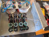
The electrolytics with the 3M tape are Mundorf'$.
Not sure if star grounding will make any difference - but I will be using this technique for the supply.
I was going to use C-L-C but couldn't fit the chokes in the case.
BTW: The surgical clamp was used to make sure there was good metal to metal contact, before soldering.
.
.
Attachments
Last edited:
When it comes to PSRR figures there is no significant differences between F5 and Aleph. F5 is a push-pull design and output devices present an active load to each other so PSRR is good for sure. If you have noise/hum troubles it's not due to PSRR - you'll have to work on you wiring (ground connections, loops etc. - star ground is essential at these current levels)
I tested a few F5 clones with just a 2 x 22.000uF per channel and they were always completely silent (tested with 94dB/1W/1m speakers). Go figure...")
I tested a few F5 clones with just a 2 x 22.000uF per channel and they were always completely silent (tested with 94dB/1W/1m speakers). Go figure...
will the very high capacitance/ciss not be a big problem ?
Tinitus,
Recall, the Bandwidth of the original F5 is in the neighbourhood of DC --> 800 MHz.
I have prototyped the F5 with these Gamut style MOSFET's and don't hear any high frequency roll off.
However, I was concerned about Q1 and Q2 being able to provide enough current
to effectively charge and discharge the increase in Ciss.
One crude technique I tried was doubling up Q1 and Q2 - I know its not pretty.
The amp became more dynamic with the doubling up.
This came down to personal taste in sonics.
Turns out N.P. used this technique in one of the Turbo versions.
.
When it comes to PSRR figures there is no significant differences between F5 and Aleph. F5 is a push-pull design and output devices present an active load to each other so PSRR is good for sure. If you have noise/hum troubles it's not due to PSRR - you'll have to work on you wiring (ground connections, loops etc. - star ground is essential at these current levels)
I tested a few F5 clones with just a 2 x 22.000uF per channel and they were always completely silent (tested with 94dB/1W/1m speakers). Go figure...
Jumo,
Interesting - I got different results.
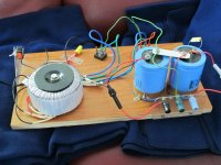
Here is a picture of my prototype supply - using computer grade electrolytics.
Note the fuses on the +/- outputs of the prototype supply.
Looking on a scope - it soon became clear the quality of the supply is key for a good F5.
Thanks for confirming star grounding is important in this case.
The ground focus point will be on the Mundorf electrolytics shown in the picture above.
Actually - I'll run a ground wire straight from the power diodes to the Mundorf's.
The amp will get its ground from that point.
.
Attachments
Last edited:
I'm really not a wire aficionado but that's clearly a sub-optimal setup - search for some successful build's pictures and you'll get it, good wiring techniques are explained and shown many times on this forum...
I'm still learning here.
I stole the idea of gluing the electrolytics down with a hot glue gun and using P to P wiring from the Blue Circle BC 1022 amplifier.
P1010474 | Flickr - Photo Sharing!
However, if I were to do it again, probably would have used an FR-4 board with a focused ground area.
But hind site is wonderful.
Also, I would have BOUGHT A PRE MADE CASE !!! instead of making it.
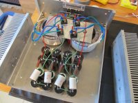
However, mounting the 2 toroids in the back of the amp worked out well - resulting in running short AC lines inside the amp.
I was a bit concerned about in rush current when the amp was switched on
so dual power switches were installed.
The technique of mounting the bridges above the power toroids seems to be pretty common.
The green wires running from the diode bridges are connected to the ground focus point.
The Mundorf film caps focus in on that node too.
.
Attachments
Last edited:
Do I spot a shorted turn between the transformers and the aluminum plate connecting them via the mounting bolts?
Lord NO !!!
There is a rubber washer - then the toroid's metal washer - and the aluminum plate sits above that.
So the aluminum plate sits at least an 1/8" above the windings.
.
Last edited:


non magnetic
btw, how is it conducting anything if its totally isolated from anything else, with isolators ?
That's the first thing Faraday asked himself too when he noticed the current flow through the conductor that was close to the moving magnet
if screw heads have connection with base plate , then also with Al plate on top - you have shorting turn through both donuts
I don't understand.
Both the case and the aluminum plate are at the same voltage potential.
The donuts are electrically insulated from the case by the large rubber washer on both the top and bottom, supplied by Antek.
Do you mean the donuts are talking to each other through the stainless steel mounting bolts ?
I thought the idea of the donut was that all the flux lines stayed inside the core ?
Can stainless steel be picked up by a magnet ?
Do they make 5/16" nylon bolts ?
Last edited:
That's the first thing Faraday asked himself too when he noticed the current flow through the conductor that was close to the moving magnet
OK - I just checked.
A 1" diameter neodymium magnet has a just a hint of a pull on a bolt (machine screw ?) made from 304 stainless steel.
Do you you think the donuts are talking to each other by inducing a current in the stainless bolts ?
- Home
- Amplifiers
- Pass Labs
- Help with F5 with Gamut style MOSFET's