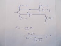
Looking at Mr. Pass's equations, for MOSFET with a high Z output stage (common source ?)
To lower Zout, the real options are:
- decrease the output source resistor
- increase F.B.
- or find a MOSFET with a low gm
Minimizing Zout is a real balancing act.
The "bricks" have a gm = 90 A/v,
So I'm thinking of going back to an Aleph style amp - but biasing it at only around 1 amp - but minimizing Zout.
I dropped the Aleph style amp only because of the power dissipation and heat.
Having a current source at each stage, has some great advantages.
.
Attachments
without curves and specific data , it's inevitable that you must do some measuring
so - either measuring xconductance of mosfets (Papa's papers 0n FW site - Mosfet Testing ) or measuring output impedance directly
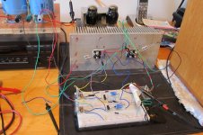
Yes, I was thinking of connecting some output resistors to the F5, measuring the change in Vout and then plot a load line.
But the Zout equations really help to understand the amp.
.
You could also parallel more output transistors. However, lowering the current through each output transistor to keep the efficiency up also lowers the transconductance for each one, raising the total output impedance. No free lunch. I've been playing around with this idea myself recently. I suspect I'm not telling you anything you don't already know.
gl
gl
one step back , two in front
anyway - capacitance will rise it's ugly head then
Had one step forward here.
Found this good article* which discusses HEXFET's in audio output stages.
There is a ton of good info in this article.
The author says because of HEXFET non linearities, a gate needs to be driven with as much current as possible to maximize linearity.
However, he doesn't look at Ciss - but instead looks at the Gate Charge.
He uses the equation I = 100 * Qg * f(max)
Turns on for a bread and butter IRF 240 Qg(max) = 70 nC
While for a Brick Qg (max) = 380 nC
This helps to explain why 3 jFET's have the poop to drive a Brick.
I would add that most datasheets show a Gate-Charge curve.
On the curve, there is a charge plateau, that is well below the max values.
* Using HEXFETs in High Fidelity Audio
http://www.irf.com/technical-info/appnotes/an-944.pdf
Yup. No free lunch.
GL,
Recommend you print a copy of this - its quite a good article.
Using HEXFETs in High Fidelity Audio
He points out that for a MOSFET Rds(on) does increase with temperature.
However, Vgs(on) has a negative Temp co efficient -1mV/oC to -1.5mV/oC
and this is why MOSFET's are prone to thermal run away.
This explains why Mr. Pass put the thermistor in parallel with Vgs.
In fact, you'd think someone would make a component that has a complementary temp co efficient to Vgs
But the best comment from the article is Compromise will be almost essential
.
.
As is Rds(on), relevant for switch mode stuff, but is of no consequence for conventional audio amps.
This is what the author says in the article - Rds(on) increases as the device gets hotter.
But this is completely useless in a linear circuit.
He says its the lowering of Vgs(on) that's important for an audio amp.
This is what causes thermal instability.
and this is why the F5 has a thermistor in parallel with Vgs.
.
In our location, it's hard and expensive to find matching numerous IRF240 MOSFET's,
so that why I take my focus on your idea. I got IXTN15N100 and PM50502C from industrial PSU board.
Can you help me prototype an amp with those mosfets.
Big thanks
Pointed,
Recall you have access to n channel devices only - so one option is building a Class A Aleph style amp.
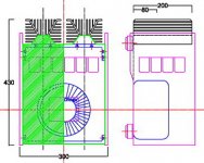
But for a Class A amp, having large heat sinks is critical.
Minimum they will need to be 4 (h) x 8 (l) x 2 " (t) 100 x 200 x 50 mm
Can you get a hold of heats sinks like this ?
.
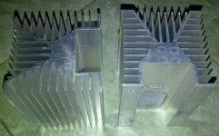
Yes, I have 4 nos, 1860cm2 each heat sink block; I intend to build Class A monoblock unit like thisPointed,
Recall you have access to n channel devices only - so one option is building a Class A Aleph style amp.
But for a Class A amp, having large heat sinks is critical.
Minimum they will need to be 4 (h) x 8 (l) x 2 " (t) 100 x 200 x 50 mm
Can you get a hold of heats sinks like this ?
.

Attachments
Last edited:
Yes, I have 4 nos, 1860cm2 each heat sink block; I intend to build Class A monoblock unit like this
Pointed,
The Heat Sinks look Great - I have a correction to make - between your 2 MOSFET options.
IXYS IXTN 15N100 and Hitachi PM 50502C
Vgs(th) ...... 2 to 4 v .............. 2 to 4 v
I cont@25 .. 15A .................. 50 A
gm (typ) ... 28 A/v .............. 40 A/v
Qg (max) ... 280 nC .............. not listed
Ciss ........... 8nF ................ 10.3 nF
I would suggest the 15N100, since Qg will be lower.
Last edited:
I intend to build Class A monoblock unit like this
Pointed,
Here are a few articles that will help you
1) DIY Op Amps
2) Using HEXFETs in High Fidelity Audio
3) A person in Sweden used "Bricks" for the output stage of an Aleph.
http://www.diyaudio.com/forums/pass-labs/91667-aleph-5-start-up-problem.html
4) Solid State Power Amplifier Supply Part 1
Except the article has 3 serious omissions
- the author should have included discussions on simple soft start ideas to control inrush current.
- a discussion between case earth and circuit ground is missing.
- the idea of star grounding is missing.
I have not heard an Aleph using IRF 9610's for the differential pair.
Later Aleph's used jFET's in the differential pair - which are known to sound softer than MOSFET's,
and jFET's also have a very good noise figure.
However, a single jFET does not have the current to drive a "Brick" off the differential pair - so I think you have 3 options
1) Stay with the Aleph that uses IRF 9610's - the schematic is ready to go.
2) Use 3 jFET's in parallel for the differential pair - bias current will need to tripled.
I haven't prototyped this.
3) Add "Bricks" to the Op Amp described in Mr. Pass' article.
Use jFET's for the differential pair, a Bi Polar for the driver stage and then the Bricks.
.
Last edited:
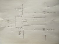
Here is the schematic of my modded F5.
Its very thermally stable and reaches full bias in about 15 minutes.
However, the high value for Zout is holding this amp back.
Mr. Pass's equations, to calculate Zout, indicate the options to lower Zout are
- decrease gm of the output MOSFET's
- increase F.B. - which will make the amp more thermally unstable
- decrease the 0R5 source resistors - which will make the amp more thermally unstable
As GL has alluded to, it seems the typical method to lower Zout is to parallel a bunch of MOSFET's in the output stage.
But that means matching MOSFET's - I'm not thrilled about this idea.
I need a Free Lunch here to lower Zout - any suggestions ?
Thermal run away occurs because Vgs(th) lowers with an increase in Temperature.
Vgs(th) lowers about 1.5mV per oC.
Other than a thermistor, is there a way to thermally stabilize Vgs ?
.
Its very thermally stable and reaches full bias in about 15 minutes.
However, the high value for Zout is holding this amp back.
Mr. Pass's equations, to calculate Zout, indicate the options to lower Zout are
- decrease gm of the output MOSFET's
- increase F.B. - which will make the amp more thermally unstable
- decrease the 0R5 source resistors - which will make the amp more thermally unstable
You could also parallel more output transistors.
As GL has alluded to, it seems the typical method to lower Zout is to parallel a bunch of MOSFET's in the output stage.
But that means matching MOSFET's - I'm not thrilled about this idea.
I need a Free Lunch here to lower Zout - any suggestions ?
Thermal run away occurs because Vgs(th) lowers with an increase in Temperature.
Vgs(th) lowers about 1.5mV per oC.
Other than a thermistor, is there a way to thermally stabilize Vgs ?
.
Attachments
- Home
- Amplifiers
- Pass Labs
- Help with F5 with Gamut style MOSFET's