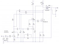
Attached is a high voltage "Schade" type SE amp that should exploit the HV capability of the ST STW7NB80 800V mosfet. These were an Electronic Goldmine special for quite some time, and I bought my share, intending to use some of them in a quasi-resonant flyback power supply operating off of doubled 115V mains. Some will indeed go there, others will go linear in this app.
The output transformer I'm using is the UBT-1, as I snagged a pair at a discount on E-pay.
I'll probably also try the Semisouth 085 in the output position with a circuit like this some time down the line, as the follower in front of the output stage would allow operation without having to worry about the 085's scandalous gate leakage current.
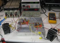
The heat sink is almost ready to mount the amp modules and output fets. If I get to it tonight, I plan to make up some output/power/feedback cables for the two amp modules. First step would be to power up the amps with bench supplies to check out bias stability and square wave response. I plan to run the amp using a largish 115-230V step-up transformer with a choke input filter. Said choke should be on its way soon from Angela Instruments.
I'll be looking at another variant of this circuit for a low voltage app without an output transformer, but that's just another thing on top of the already teetering pile of projects.
The output transformer I'm using is the UBT-1, as I snagged a pair at a discount on E-pay.
I'll probably also try the Semisouth 085 in the output position with a circuit like this some time down the line, as the follower in front of the output stage would allow operation without having to worry about the 085's scandalous gate leakage current.
The heat sink is almost ready to mount the amp modules and output fets. If I get to it tonight, I plan to make up some output/power/feedback cables for the two amp modules. First step would be to power up the amps with bench supplies to check out bias stability and square wave response. I plan to run the amp using a largish 115-230V step-up transformer with a choke input filter. Said choke should be on its way soon from Angela Instruments.
I'll be looking at another variant of this circuit for a low voltage app without an output transformer, but that's just another thing on top of the already teetering pile of projects.
Attachments
I spent a while tonight making up cables and power supply leads (serenaded by enough firecrackers for WWIII), so this amp will soon be ready to slap down on the heat sink for a first power-up with bench supplies. I'll run it open loop at first, but if it's anything like the "SiC Puppy", a little feedback around the output transformer will be beneficial in cleaning up the square wave response. I may have some preliminary sound out of this thing by the close of the weekend.

Amp is up and running on bench supplies, and sounding just as nice as all the other single ended projects I've done lately. Once I fixed an open solder joint, both channels came up without any protest. I need to change the bottom resistor in the bias/Schade feedback network for the output to get the bias current up a bit (it's 130mA vs. the planned 150 mA), but that's just the difference between the simulated device and actual. Stability does not appear to be an issue.
Next will be to gin up a power supply and enclosure for extended listening, as the heat sink I'm using is not at all challenged by the power dissipation.
Next will be to gin up a power supply and enclosure for extended listening, as the heat sink I'm using is not at all challenged by the power dissipation.
Attachments
Just about any mosfet rated 600V and above should work in this amp. I suspect that even 500V would be ok in most places, but I want to be safe in a case where the amp is slammed into saturation with a light output load. There are lots of candidates, including a whole mess of 600V IGBTs. No one so far has proposed using IGBTs in this kind of amp, but I see no reason against it.
It turns out Michael Koster has tried the Schade dodge with an IGBT, using a somewhat different circuit...
http://www.diyaudio.com/forums/tube...r-triode-strapped-pentode-12.html#post2207735
http://www.diyaudio.com/forums/tube...r-triode-strapped-pentode-12.html#post2207735
Koster's implementation is similar to Pete Millett's "E-Linear" amp - another way to skin the cat. Pros and cons - no coupling caps, but a cap (the "Ultrapath" cap) that is tied up with whatever is happening with the power supply. Also, lots of dissipation in the source resistors for the output stage. Still, it's another approach. I had a look at the 1kV IXYS depletion mode FETs used for the input - I have a tube of these I haven't broken into just yet. Compared to the DN2540 Supertex parts, the input capacitance is a lot lower - 100pF vs 300 for the DN2540N5. Having said that, the Supertex part sounded nice in the "SiC Puppy".
At any rate, it's nice to have more circuit options to try. The IXYS part could be used to cascode other parts that have even lower input capacitance, such as my favorite of the moment, the 2SK117, or the J309/310, as used in the current implementation of this amp....
At any rate, it's nice to have more circuit options to try. The IXYS part could be used to cascode other parts that have even lower input capacitance, such as my favorite of the moment, the 2SK117, or the J309/310, as used in the current implementation of this amp....
I may add - I always add an input coupling cap to my amps. as I can't vouch for the purity (the lack of DC offset) for any source they might encounter. I have been castigated for this and other additions from individuals who will remain unnamed (they wouldn't know anyways, since I'm supposedly on their "ignore" list). I prefer stuff that can play in an imperfect world. A minimum-components implementation is just that - not necessarily the best sounding.
I may drag this setup in to work to play on the HP4194A gain-phase analyzer, as I'm curious as to how the UBT-1 outpit transformers will look. On my "SiC Puppy" Amp, I have two UBT-1s of different vintage, and they appear to have very different frequency response characteristics. I may swap transformers between channels to see if the problem migrates, but not right away...
To answer my own question, I took an educated/wild guess and a value of 68k for R13 seems to work the best. Actually, I just started off with a value of 10k and ran a few sims to see which way the wind was blowing.
I substitued an FQA1190C_F109 (what a mouthful) for the STW7NB80 because I could not find a SPICE model. For the transformer I used a model for a Trace-Elliot 15W that I had on hand.
The simulation shows about 7W into 8 ohms at 1kHz with 3.7% THD. Am I in the ballpark with these results?
I substitued an FQA1190C_F109 (what a mouthful) for the STW7NB80 because I could not find a SPICE model. For the transformer I used a model for a Trace-Elliot 15W that I had on hand.
The simulation shows about 7W into 8 ohms at 1kHz with 3.7% THD. Am I in the ballpark with these results?
Attachments
- Status
- This old topic is closed. If you want to reopen this topic, contact a moderator using the "Report Post" button.
- Home
- Amplifiers
- Pass Labs
- Das ist aber Schade...