The power supply might be a bit close rated given the 1.45 A per channel quiescent current... however this is what I would do.
1/ Concentrate on just one channel at a time. That means disconnecting the supply to the channel you are not working on.
2/ Fit shorting plugs to both inputs.
3/ Check the basic voltages that will show what the state of play is with the amp.
These are firstly confirming the supply is correct at 24 volts.
Now check that the voltage on the speaker coupling cap (+ end) on the channel you are working on is approximately 12 volts and is correctly adjustable.
Checking the quiescent current by measuring the voltage across R1 and calculating the result using ohms law. 1.45 Amps should measure as 0.34 volts. Remember there are two 0.47 ohms in parallel and so the effective resistance is 0.235 ohm.

Have photos in iCloud, but don't know how to put them here. Crenova multimeter only diagnostic tool I have.
This might help:
iCloud: Create a shared album with iCloud Photo Sharing
Or you could just upload the images to the forum (as long as they re not too big)
dave
URL for photos requested. Don't know how to provide. Should've mentioned I suppose, that both pcb's worked fine before when IRFP240's were wired to board because heatsink holes didn't align with pcb. Only thing I changed is soldering output transistors directly to pcb. I'm checking all I can with my meter now. Will post numbers. Thanks
DIY ACA project : THD% data after R15 modification
I added the R15 modification to my ACA circuit boards this evening. The resistor had to be elevated above the board as not to cover the bias test point.
The THD vs. Output Power measurements improved dramatically and were similar to data published by Pass Labs.")
THD + N @ 1W = .7%, 2W = 1%, 3W = 1.4% 1KHz sine wave test signal.
Both channels had similar THD +N performance.
I will look at square waves and determine onset of clipping at a later time.
dt 667
I added the R15 modification to my ACA circuit boards this evening. The resistor had to be elevated above the board as not to cover the bias test point.
The THD vs. Output Power measurements improved dramatically and were similar to data published by Pass Labs.
THD + N @ 1W = .7%, 2W = 1%, 3W = 1.4% 1KHz sine wave test signal.
Both channels had similar THD +N performance.
I will look at square waves and determine onset of clipping at a later time.
dt 667
Attachments
Snip
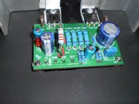
Holly thermal grease batman
You do know that thermal grease is only meant to fill in the tiiiiny little voids between the surfaces.
The thinnest smear is ample.
There's enough on yours to mount 20 devices.
Holly thermal grease batman
You do know that thermal grease is only meant to fill in the tiiiiny little voids between the surfaces.
The thinnest smear is ample.
There's enough on yours to mount 20 devices.
yeah , and extremely bad soldering everywhere
that begs for some practice beforehand (on junk pcbs , desoldering , soldering again) and just then thorough cleaning and re-solder of ACA
sarathssca,
Yours does work! Soldering could be better, but the board side picture is not that bad. There is much worse soldering to be seen... Yes a little too much thermal goop, mind you do not get it in your eyes, seriously wipe it away. You do really only need a small blob, less than half a grain of rice, next time.
OnC / ZM Come on guys, we all started somewhere. And sarathssca has been asking for advice.
Chris & i switched the system to ACA monoBlokks yesterday. That required changing the preamp too (and the speaker wires — couldn’t find my single bananas, and monoBlocks don’t allow for use of our favorate dual Pomonas (i might fix that). Overall a good change, the speakers appreciate the extra power..
dave
dave
Have you actual measured that you use the extra power which means that you reach clipping level with "standard" SE ACA?
If not you get half damping factor (2 x output impedance of single ACA) running ACA in bridged mode. A single ACA should have better bas control assuming speakers are sensitive enough so extra power is not needed?
If not you get half damping factor (2 x output impedance of single ACA) running ACA in bridged mode. A single ACA should have better bas control assuming speakers are sensitive enough so extra power is not needed?
- Home
- Amplifiers
- Pass Labs
- Amp Camp Amp - ACA