Thanks Zen Mod. To confirm, I turn it off, unplug it, open the case, and use the multimeter to check that resistors are same as spec. If not, then replace ones that are not to spec?
It can save everyone a LOT of time if you can post some clear photos.
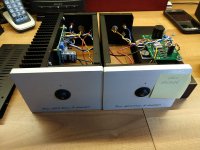
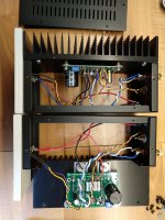
overall pic of entire unit.
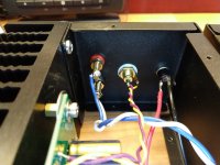
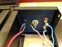
pic of inside back panel.
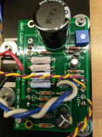
pic of left channel.
pic of right channel.
Errors can sometimes be spotted by eagle eyed snoops
")
Old 'N Cranky, I like eagle-eyed snoops, especially when they are helping me. To late for assembled pics, I've already pulled them apart. Zen Mod, the resistors check out visually. The one that I couldn't see I measured, and it came in as per spec.
Three photos attached, have a peek. 2 more in a post following.
Three photos attached, have a peek. 2 more in a post following.
Attachments
Last one.
Is it distorted? Or, just low in volume?
Well it seemed to be just low volume. But to be honest it was so low it could have been distorted and I would not have noticed. When I get them back together I will check for distortion.Is it distorted? Or, just low in volume?
Well it seemed to be just low volume. But to be honest it was so low it could have been distorted and I would not have noticed. When I get them back together I will check for distortion.
take an alligator clip, or screwdriver and short the power switch. If that does not help. Unplug the power supply from the power connector and connect the center conductor of the supply to the side of the switch that feeds the circuit board and the connect the outer conductor to ground.
I had one that ran me in circles for a few minutes when I first built mine - because the connector center conductor could pass enough voltage and current to light the LED - but not enough current to run the amp. It ran fine for about 12 hours and when I turned it on the next morning it did not work.
May or may not help - but hope it does! If not, you will know one more thing it isn't... : )
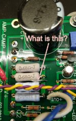
There is a foreign object in there.
Get it out before going any further...
Good luck, Alan
I'll be danged and hanged, you are correct. I never even noticed. It appears to be a little bit of unused solder. Probably been there since it was built, because these things have not been opened up since building and testing.
Thanks, Alan! I'll keep you guys posted on how it goes.
On my ACA amp the RCA is a little loose. I will occasionally get lower than normal volume out of it, especially if I had been messing around with the cables behind it. My RCA is a little loose and I can get full volume back by jiggling the cable and RCA jack. I would check that and the binding posts first before looking at the board.
Last edited:
Yes. No change in right amp, so it does not appear to be power supplies.Did you swap the power supplies between the amps?
The RCA connectors can be a little tricky to fasten to get a good GND connection. It would be better with a type which has a hex-shape (instead of round) so you can get some pressure on the GND solder connection. There are also types like these:
CMC(R)-Charming Music Conductor.
where you solder direct on the "frame" (nice stuff). So no chance for a bad GND connection.
CMC(R)-Charming Music Conductor.
where you solder direct on the "frame" (nice stuff). So no chance for a bad GND connection.
Some of that soldering looks a little sketchy - you could try a solder reflow job, touching each point with an iron until everything looks smooth.
If that doesn't work - since you have a working amp and a non-working, I would take DC measurements with your DMM at various point in the circuit and compare the good versus the bad. This is, of course, with the power on. Be careful not to short anything out, etc with the test probes.
Also check the ohms - power off - of R11 and R12 the feedback resistors. Make sure they match the circuit.
Note: I'm usually a tube guy and will be building my ACA amps when they come sometime this summer. I'm sure someone with a SS background could offer even deeper troubleshooting tips.
edit: And Mr. Pass beat me to it.
- Home
- Amplifiers
- Pass Labs
- Amp Camp Amp - ACA