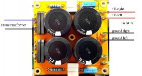
Based on your pcb pic: simply connect 1 blue and 1 black wire from your transformer output to the 2 x AC connectors located on top left. Put some electrical tape on the end of the unused blue wire. By doing so you will get a DC voltage of about 20V across the Gnd and V+ connections on the right side of your pcb. The ACA does not require a negative voltage to work. Just connect both channels to the Gnd and V+ this way you’ll be able to use your transformer.
What about the left side? According to your configuration, only 1 side can be used.
Then another unused will be wasted. 30000uF sharing one channel?Exactly, you can only use 1 set of the AC input if you have 3 wires on the secondary of your transformer. The bottom 2 AC connectors must remain unused.
Last edited:
I don't hv the pcb diagram. I bought this in ebay.
Any idea how?
go back to post where I posted pics and info for 2 diode full rectifier
remove both diode bridges and caps from pcb , connect per above info directly with wires
no way that you can use existing pcb for ACA , at least no if you don't know what you're doing (cutting traces and making new traces with wire; tutorial for that is sorta hard to make , without having pcb in hands ...... looking just at pictures is recipe for fookoop)
be creative
Last edited:
According to your post I need another center tap transformer. I think I can understand from the pictures.go back to post where I posted pics and info for 2 diode full rectifier
remove both diode bridges and caps from pcb , connect per above info directly with wires
no way that you can use existing pcb for ACA , at least no if you don't know what you're doing (cutting traces and making new traces with wire; tutorial for that is sorta hard to make , without having pcb in hands ...... looking just at pictures is recipe for fookoop)
be creative
Remove both diode bridges and caps, and connect directly, mean connect the transformer directly to ACA?
why would you need 2 xformers ?!?
you have one , use what you have
if you want dual mono ( as I made), then buy another one
connect bridges and caps directly with wire (according to sch on link I posted previously), without pcb ......... just because you can't use this one
if you
you'll make one big bang , no amplifier
point is - to use what you have , you need to reach bottom (to fully understand) of circuit you need to use (2 diode full rectifier arrangement)
sometimes pure visual Lego/Puzzle approach isn't enough , you must invest some elbow grease
you have one , use what you have
if you want dual mono ( as I made), then buy another one
....
Remove both diode bridges and caps, and connect directly, mean connect the transformer directly to ACA?
connect bridges and caps directly with wire (according to sch on link I posted previously), without pcb ......... just because you can't use this one
if you
....
......connect the transformer directly to ACA?
you'll make one big bang , no amplifier
point is - to use what you have , you need to reach bottom (to fully understand) of circuit you need to use (2 diode full rectifier arrangement)
sometimes pure visual Lego/Puzzle approach isn't enough , you must invest some elbow grease
Last edited:
Ok i think i get what you mean. Just remove the parts from the pcb n reconnect it with wires so that i can use back all the 4 caps.why would you need 2 xformers ?!?
you have one , use what you have
if you want dual mono ( as I made), then buy another one
connect bridges and caps directly with wire (according to sch on link I posted previously), without pcb ......... just because you can't use this one
if you
you'll make one big bang , no amplifier
point is - to use what you have , you need to reach bottom (to fully understand) of circuit you need to use (2 diode full rectifier arrangement)
sometimes pure visual Lego/Puzzle approach isn't enough , you must invest some elbow grease
Oh yes. I understand now but doing this am i using only 100va from the transformer? Will this be enough?NO!!!!
That would go puff.
s'pose what ZM meant was desoldering your psu board and use the parts according to his suggested schematic.
Wiring a simple psu is no witchcraft - you'll make it. take a perfboard.
Be confident!
A.
Ahhh ... too late again...
moppy,
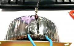
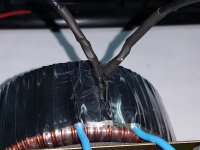
are you shure your centertap is just one wire?
the CT transformers I've seen so far have two wires in one isolation hose and were just soldered at the tip. take a close look!
A.
from picture , center tap connection is buried under plastic tape and whatnot
Oh yes. I understand now but doing this am i using only 100va from the transformer? Will this be enough?
two diode full wave rectifier is engaging all 3 wires from secondary
result - you're using entire potential of xformer
remember - playing with mains voltage is lethal
better stay competent in own field , having someone else doing other field work .....
remember that best part of building anything is actually learning new things .
learn , then do
OK will have a closer look. The transformer is in my office, will check it on Monday and post the picture too.moppy,
are you shure your centertap is just one wire?
the CT transformers I've seen so far have two wires in one isolation hose and were just soldered at the tip. take a close look!
A.
Will check it again on Monday. Thanks.from picture , center tap connection is buried under plastic tape and whatnot
Yes, agree. I have learn a lot from here. Again thanks for your replied.two diode full wave rectifier is engaging all 3 wires from secondary
result - you're using entire potential of xformer
remember - playing with mains voltage is lethal
better stay competent in own field , having someone else doing other field work .....
remember that best part of building anything is actually learning new things .
learn , then do
moppy,
are you shure your centertap is just one wire?
the CT transformers I've seen so far have two wires in one isolation hose and were just soldered at the tip. take a close look!
A.
I saw 2 wires joined together. Here what I do. I use meter to check the continunity test. Each blue wire only beep with 1 black wire. I think there's no shorting at all. Therefore, now can I use this for my power supply?
Zen Mod, what do you think? I guess this is easier for me to take every parts out from the pcb and reconnect it with wire.
Attachments
Last edited:
- Home
- Amplifiers
- Pass Labs
- Amp Camp Amp - ACA