

") . Just making more of a toy for computer than a serious amp, that's why I am so ... What is the word... cheap
. Just making more of a toy for computer than a serious amp, that's why I am so ... What is the word... cheap 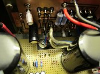
val
hi
these values are valid for P.S. 13 volts and 4 ohms loudspekers?
thanks
It looks like all the transistors are functioning correctly. The problem must be that one or more of R1, R2, R3, R4 are not the correct value, or current is flowing through C1 to the speaker.
The voltage from the Drain of Q1 to the plus side of C1 should be 0.366V and 0.253V from the plus side of C1 to the Source of Q2. A low voltage on one side points to which side has too low a resistance. If the sum of the voltages is not 0.62V, some current is flowing in C1 or somewhere else.
With no signal, the DC voltage at the speaker (-Out on the schematic) should be very close to zero volts. Verify that the polarity of the capacitor is correct. I made a mistake on one of my builds. I connected the +Out to +19V instead of ground.
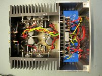
Note that it's a good idea to mount transistors low on the heatsink for best cooling efficiency. The top of a heat sink is usually several degrees warmer. I suggest about 1/3 the length from the bottom.
hi
these values are valid for P.S. 13 volts and 4 ohms loudspekers?
thanks
I experimented with the ACA on the bench with a 13.3V rail and a 4 ohm load. There was a raise in distortion at 1 Watt. The cure for that was to increase the idle current in Q1 and Q2. What I did was solder and additional 0.47 ohm resistor in parallel R1, R2 and an additional 0.68 ohm resistor in parallel with R3, R4. That moved the distortion curve down near the stock ACA with a 19V rail and an 8 ohm load.
Adjusting the pot affects the distortion. With a 13V rail, about 7V will give the most headroom. I posted a graph somewhere in this thread for different ouput voltages with a 19V rail.
Adjusting the pot affects the distortion. With a 13V rail, about 7V will give the most headroom. I posted a graph somewhere in this thread for different ouput voltages with a 19V rail.
Though I should have done this earlier, too many constraints had denied me the opportunity thus far; but I have now completed a single-sided PCB layout for the ACA. I am going to try an SMPS as well as a conventional one to check the sonic differences. I will be using a 18-0-18 120VA torroid. I guess it is just about sufficient. I have made the provision to switch the cap bank out when using an SMPS. Made provision for a BF862 along with a resistor in the Drain.
Questions are, the value of the resistor, assuming about a 24VDC linear supply when testing with BF862?
Although I would be driving Fostex FE168Sigmas, I just thought adding a peak power indicator or clipping indicator would be added insurance. Any pointers to a circuit?
Thanks,
Sam
Any feedback on the quoted post? Thanks.
We sent a kit to Papa Pass and he wrung it out with his test gear...
Turns out it can be tweaked to have more bias and put out the full SIX watts, with less distortion!
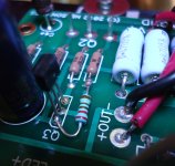
You have to add R15, Value 2.21K
Turns out it can be tweaked to have more bias and put out the full SIX watts, with less distortion!
You have to add R15, Value 2.21K
Attachments
Last edited:
Here's a photo of how to tweak the ACA to have 6 watts output and lower distortion! Higher bias is the ticket and it's simple!
Just use a 1/4 or 1/8w 2.21K metal film resistor and solder it in place as shown here..
Just use a 1/4 or 1/8w 2.21K metal film resistor and solder it in place as shown here..
Attachments
Last edited:

- Home
- Amplifiers
- Pass Labs
- Amp Camp Amp - ACA