Eric (or anyone else who collected ACA parts themselves):
Did you tap threads into the heatsink or simply drill holes and use small bolts/nuts for fastening PC board and MOSFETs to heat sink?
Any tips for someone who's never done metal work and needs to drill holes in heat sink (beyond some of the threads in Construction Tips - heatsink holes)?
Thanks!
Did you tap threads into the heatsink or simply drill holes and use small bolts/nuts for fastening PC board and MOSFETs to heat sink?
Any tips for someone who's never done metal work and needs to drill holes in heat sink (beyond some of the threads in Construction Tips - heatsink holes)?
Thanks!
Before you drill the hole, use a hammer and nail sinker to score where you will drill.
This prevents the drill bit from walking from the spot where you want to place the hole.
If tapping after drilling, use wd-40 to lub and turn the tap in 1/4 turns, back out and continue with another 1/4 turn, back out a 1/4 turn, and so on.
You might want up try self tapping screws, if no tapping tools available, but the screws are not pretty, not like button head or hex key screws.
Eric (or anyone else who collected ACA parts themselves):
Did you tap threads into the heatsink or simply drill holes and use small bolts/nuts for fastening PC board and MOSFETs to heat sink?
Any tips for someone who's never done metal work and needs to drill holes in heat sink (beyond some of the threads in Construction Tips - heatsink holes)?
Thanks!
I tap threads into the heatsink, I bought some 6/32 screws and drilled all holes with a 7/64 bit and then used the 6/32 threading tap. Doing this is aluminum is very easy. Put some light oil or WD-40 while threading and you are all set. Before doing it on your heatsink, why not practice on another piece of aluminum, you'll see it's fun and easy.
p.s. My previous pics showing the 3 bolts (3rd pic of post no.950) were just to show the required height of a stand-off I don't have.
Rgds,
Eric
Last edited:
Hi,
Newbie questions:
- What is the "more correct" position of the outer leg of P1: in the junction between (R1-R2-R3-R4-C1) or (R3-R4-Q1)? I saw this difference between schematic and PCB in Mr. Pass's article and tried both in my prototype but saw no difference in operation.
- What is the main purpose of the 4 resistors R1-R4, beside of biasing?
If I use R1=R2=0.68R, R3=R4=0.47R; or R1=R2=R3=R4=0.56R (bias will be the same), what will be the difference?
Or if I replace those by only one resistor 0.56R (same bias, but C1 & P1 will be connected to Drain of Q1), what will be the difference?
Rgds,
Duong
Changing the connection to P1 doesn't make much difference, but slight changes in the bias voltage will change the measured distortion (and the gain). Search for some of my earlier posts in this thread for graphs.- What is the "more correct" position of the outer leg of P1: in the junction between (R1-R2-R3-R4-C1) or (R3-R4-Q1)? I saw this difference between schematic and PCB in Mr. Pass's article and tried both in my prototype but saw no difference in operation.
R1, R2, R3, and R4 set the bias current, but they also control the ratio of signal sent to Q2. This in turn changes the linearity and distortion profile of the amp. Making them equal will increase the distortion and will reduce the gain, but you may like the sound. I think Nelson found a good compromise between measured performance and listenability. In the PLH article Nelson discusses this. Link: https://www.passdiy.com/pdf/PLH_amplifier.pdf- What is the main purpose of the 4 resistors R1-R4, beside of biasing?
If I use R1=R2=0.68R, R3=R4=0.47R; or R1=R2=R3=R4=0.56R (bias will be the same), what will be the difference?
Notice how C2 is connected to the bottom side of R3, R4. When Q1's current is reduced in response to a negative going input, Q2 is encouraged to turn on more. So Q2 does not act like a constant current source, but more like a negative resistance (current goes up as the voltage goes down). As Nelson discusses in the ACA article, you can play around with the ratio of R1, R2 to R3, R4.
Q2 would become a constant current source. The distortion will be higher, gain lower,Or if I replace those by only one resistor 0.56R (same bias, but C1 & P1 will be connected to Drain of Q1), what will be the difference?
Changing the connection to P1 doesn't make much difference, but slight changes in the bias voltage will change the measured distortion (and the gain). Search for some of my earlier posts in this thread for graphs.
R1, R2, R3, and R4 set the bias current, but they also control the ratio of signal sent to Q2. This in turn changes the linearity and distortion profile of the amp. Making them equal will increase the distortion and will reduce the gain, but you may like the sound. I think Nelson found a good compromise between measured performance and listenability. In the PLH article Nelson discusses this. Link: https://www.passdiy.com/pdf/PLH_amplifier.pdf
Notice how C2 is connected to the bottom side of R3, R4. When Q1's current is reduced in response to a negative going input, Q2 is encouraged to turn on more. So Q2 does not act like a constant current source, but more like a negative resistance (current goes up as the voltage goes down). As Nelson discusses in the ACA article, you can play around with the ratio of R1, R2 to R3, R4.
Q2 would become a constant current source. The distortion will be higher, gain lower,
Looks like I've missed some parts in Mr. Pass's article.
Anyway now I'm digging the 99 pages of this thread, and will take another look at the article, hope this will help.
Thanks very much,
Check out Heatsinks USA. They have several products with a 1/4" back web the allow blind threaded holes. They will cut to customer specs, or you can use a carbide blade on a table saw. Depending on what you are building, PC CPU heatsinks come in a bunch of shapes and sizes and are low cost on eBay. See ex. HERE
Last edited:
Check out Heatsinks USA. They have several products with a 1/4" back web the allow blind threaded holes. They will cut to customer specs, or you can use a carbide blade on a table saw. Depending on what you are building, PC CPU heatsinks come in a bunch of shapes and sizes and are low cost on eBay. See ex. HERE
Sorry, I should have been more clear. I'm referring to this material:
Quasi Heatsinks
I don't need it for a heatsink but as a side to build a temp case. I'm looking for something that I could attach the heatsink to, perhaps with a bolt, nut and t-slot.
Any ideas for a cheap aluminum enclosure that would accommodate attachment of the heatsinks they sold in the DIY store would be great.
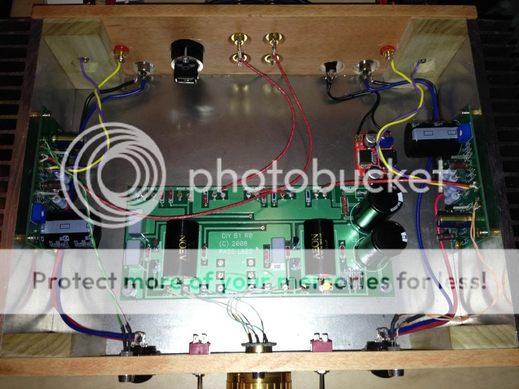
I use wood for the front and rear and the heatsinks from the store as the sides.

Billy-
Nice and elegant. I see that you made that an integrated.... nice!
Are the smaller blocks glued to the front/back panels? I assume you bolt the heatsinks to the smaller inner blocks and mount those to the front/back panels?
What are you using for a top/bottom cover?
Nice and elegant. I see that you made that an integrated.... nice!
Are the smaller blocks glued to the front/back panels? I assume you bolt the heatsinks to the smaller inner blocks and mount those to the front/back panels?
What are you using for a top/bottom cover?
O.K. Try the links on THIS POST for some T-Slot materials. Not sure if it's what you need.
Sorry for not seeing that from your previous link. Thanks for that again.
Billy-
Nice and elegant. I see that you made that an integrated.... nice!
Are the smaller blocks glued to the front/back panels? I assume you bolt the heatsinks to the smaller inner blocks and mount those to the front/back panels?
What are you using for a top/bottom cover?
Thanks!
I added an ODAC to it and have it on my desk at the office. Sounds great, makes my day go by easier.
Exactly what I did, had to use gorilla glue, the wood glue did not hold on one corner. Prolly expansion contraction thing. For the bottom I used some sheet steel from Home depot for the top I used plexi st show off my handiwork.
 good use of wood.
Sorry for not having the ACA chassis up for presale by now. I was sick in bed all week complete with an amusing trip to hospital for some referred pain issues that had me thinking I was in serious trouble and this has put everything back a week (everything is just fine now). I just need to trick up the store to handle the presale stuff and it's good to go. At the moment though I'm spending some time on hardware / software optimization on the server, things are looking good, in 24-48 hours things will be even better...
Would you have all the benefits of monoblocks if you copy cat Eric but use 2 power supplies & 2 switches? Eric that is one gorgeous amp you & your daughter assembled! Would I have to isolate each side with aluminum boxes enclosing the PCBs & attached to the heatsinks? To reduce EMF?
Another newbie question.
Can the RCA barrel touch a metal enclosure, or do they have to be perfectly isolated from the chassis?
Another newbie question.
Can the RCA barrel touch a metal enclosure, or do they have to be perfectly isolated from the chassis?
- Home
- Amplifiers
- Pass Labs
- Amp Camp Amp - ACA