Don't want to hijack the thread too deep into speakers, but there is an interesting design that should sound good with the ACA. I haven't had time to make the combination yet, but will do so soon.
Foam Core Board Horn.
Foam Core Board Horn.

You could just leave off R1 and R3 and that would cut the current in half. I suspect the distortion would increase because Q1 would be farther into it's non-linear zone and open loop gain would be reduced. The distortion will be low order, you might actually like the sound. I like listening to mine with the feedback disconnected. Just remove R12. My latest build (#6) has a pair of IRF520s. They have a flatter distortion at 1W graph.
Loudthud,
When you said just remove R12 for the no feedback, you meant to just put a piece of wire in place of R12 or just dont install it at all (for standard build.) Can i also remove R11. Thanks.
Last edited:
I meant don't install it. My ACAs are all built on proto board, I installed little computer style jumper blocks in series with R12 for quick changes. I left R11 in place just as a way to limit gate current of Q4 when the amp is overdriven. (I'm prone to doing that when using the ACA as a guitar amp.) You would replace R11 with a wire if you want to try that. It may lower noise and extend the high end slightly.Loudthud,
When you said just remove R12 for the no feedback, you meant to just put a piece of wire in place of R12 or just dont install it at all (for standard build.) Can i also remove R11. Thanks.
Quote:
I have built the ACA and I have found the sound a little "laid back".
The speaker impedance can affect the sound, but it might also be the absolute phase. The ACA simple design inverts the phase. To correct that Mr. Pass has the + terminal connect to the common in the design so that the phase will be inverted back to original. If you by chance have the - terminal connected to common, try reversing the polarity to the speakers. An inverted absolute phase tends to "truncate" the soundstage toward the middle and back. It might be a long shot, but worth mentioning. Some recordings are processed to end up with inverted phase and will sound better with reversed polarity. At least you will be able to recognize when this happens.
I use a separate P.S. to each channel and it sounds neutral to me into 8 ohm speakers.
I have never before in my life DIY'ed a ClassA amplifier, but this little AMP_CAMP #1 amplifier attracted my ambition,
and I did a single-sided layout by myself and will etch and build it.
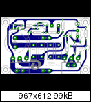
http://www.abload.de/img/aca_1x4kit.png
There is only one wire (from bottom-VCC to SK170-VCC) to be inserted manually!
The size of the PCB is 73 x 46 mm.
I do not know, if I am allowed to show you my layout (I did not ask Mr. Nelson Pass for permisson), and I do not want to
compromise anybody's group-buy!
But here it is!
Best regards - Rudi_Ratlos
Attachments
All right now....
Hi friends,
I have now resolved my problem. I had on hand a pair of Fostex FE83en loudspeakers and I tried them. Absolutely fantastic sound!!!
There is a small amount of lacking bass but this is speaker fault. Now I am in the way to build a better FR with the CSS EL70 drivers.
Thank you all for your suggestions.
Happy new year!!!
Regards
Last edited:
I probably missed it somewhere in the thread, but what's the status on future amp camp amps? I'd like to try the class A route and this is affordable and has a solid name behind it.
Any more amps going to be offered in the future? I signed up for the mailing list, but am wondering if there's a time frame estimate.
Thanks,
Mike
Any more amps going to be offered in the future? I signed up for the mailing list, but am wondering if there's a time frame estimate.
Thanks,
Mike
Last edited:
Q1 set at 10 volts DC
Hello
My ACA is also running
But i think i will run it at higher Rail voltage, because my psu deliver a bit more than 19V.
Burning down the Voltage with resistor to desired level will produce a lot of heat -wanted to avoid this.
Now i dont know should i also set Q1 at 10V or is it different at higer Rail voltages?
Ive read the artikle but i already dont know why there are 10V?
Help needed thanks
Right now, I am using the ACA in my office, connecting the RCA outs from a M-Audio 2496 sound card on my computer, using the M-Audio app to control the volume. Works real well, sounds great with my Zaph|Audio ZA5.2s. Try Dead Can Dance "Into the Labyrinth" as a test album!
Hello
My ACA is also running
But i think i will run it at higher Rail voltage, because my psu deliver a bit more than 19V.
Burning down the Voltage with resistor to desired level will produce a lot of heat -wanted to avoid this.
Now i dont know should i also set Q1 at 10V or is it different at higer Rail voltages?
Ive read the artikle but i already dont know why there are 10V?
Help needed thanks
Generally the voltage is set to give maximum output before clipping. Because the ACA is not totally symmetrical, the voltage is not exactly half the power supply voltage. Experiments have shown that the higher the voltage is set, the less dramatic the 1 Watt distortion raise is at higher frequencies. I posted a plot of this in post 576 of this thread. I theorize that this is because the gain starts to fall off as the output voltage swings positive and the effect and amount of Q1's non-linear gate capacitance is also increasing. If you don't have an oscilloscope, start at half the supply voltage and try small changes to see if you can preceive a tonal change. Note that the voltage set by P1 does not change if the supply voltage changes, only a small temperature drift.
But i think i will run it at higher Rail voltage, because my psu deliver a bit more than 19V.
Burning down the Voltage with resistor to desired level will produce a lot of heat -wanted to avoid this.
There's lots of margin in this design. As long as your original voltage is
not really much larger, I suggest you use it, and set the Drain voltage
at approximately 1/2 of the supply.
- Home
- Amplifiers
- Pass Labs
- Amp Camp Amp - ACA