Along with the higher transconductance comes higher input capacitance. I tried IRFP460s and the results were poor. It could be that R6 needs to be lower, I didn't try that. I tried running three Q4s in parallel with R9 at 220 ohms and the results didn't improve much. Q1 becomes very non-linear as the Drain voltage dips below the Gate voltage. Visible distortion at 1kHz. At that high a rail voltage, you will need gate protection zeners. I'm going the other way. Next I'm going to try IRF120s. Suggest you search for my posts in this thread.
I went through the thread again and found all your useful posts. I missed the post where someone mentioned using BF862 instead of K170. It appears that the stock version is pretty much optimized. Ofcourse, the bias can be doubled for double the pleasure. So for the present IRFP240 it is. Your results with IRF120s would be interesting. I have some unused IRF620s.
One question - IIRC JLH had mentioned about lowering distortion by using a Darlington BJT for the lower output device. Any comments?
Mike, have you found the way to optimize the design for 15ohm load?Ok got this finished at last. Couldn't trace the mains hum I was getting on one channel but after discovering it went away when the two mono blocs touched the way forward was obvious
Apart from the kit and sinks from the store I spent £10 on aluminium angle from a hardware store and £10 for two pc power supplies on the bay uk.
The amp sounds great....great power, bass and massive detail. Probably loses just a little smoothness in the mids compared to my tube/valve gear but not by much. Amazing amp for the build cost. The amp is dead silent between tracks and the sinks get warm but still ok to touch after 30 mins. I'm driving 15 ohm speakers with it....anyone know if it needs optimising for this load compared to 8 ohm? I got some spare boards and will probably have a go at a version with a "proper" power supply at some point. Anyone got any thoughts on a power supply?
Mike
Hi Commstech
I'm afraid not yet. To be fair the stock amp sounds very good indeed with my vintage 15ohm 3 way Wharfedales (no problem driving the 15" woofers) so I wouldn't let it put you off building it if you have 15 ohm speakers.
That said if anyone more clued up would like to chime in that would also be cool.
Mike
Just waived goodbye to Macfixer after fun afternoon!!
Amps go together so easily! Really a great initiation! I completed mine up to the stage where I would mount the board to the heat sink and left it there as I have yet to finalise my chassis arrangements.
We completed one of Macfixers and let it warm up as per the build notes. Then a first listen via a pair of Minimus 7's to check all was well. Sound was big & full.
so onwards to my Emkens
Cant wait to finish my amps and get it up and running. Will post pix once I've finished mine and chassis is built.
Only issue is a thump at turn off - all in all not bad for an afternoons work
first off thankyou James for walking me through my first build,it was a bit tricky a first but the music kicked in and it all flowed great. I had to leave quick in eeded to plug those amps in at home............................now its friday and it late. What a week not a lot of macfixing but got the system sounding alright.
Firstly thankyou Nelson and all at DiyAudio....it sure do sing sweet ad lots of grunt. the family frendly system is firestone spitfire Flacs with burr brown upgrade through bi-amp quad 306es into B&W 603, a very friendly system.
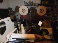
All week if been tinkering with the ACA from a heybrook TT2 with a cardridge given to me so i can go through my vinyl and it been a bitter sweet time of extreme highs and lows......no one likes it.....but cant you see the boxes are to small etc etc i have FE206e shouting so phase plugs in gunck and felt applied still not sounding right, questioning do i want to invest in the ply to build the BIBs. Got desperate took the tweeter out of some old linn speakers wired up an alps took another output from the pre and buggered about with te volume to just colour the bottom a bit.......Ok sounds more presentable.
So tonight Ive gone an plugged in the dac and played some Flac.......joy joy happy happy joy joy.
God i love that amp and my cartridge is ****!
Attached the most Flugly room youve seen in a while it was clear on Monday
So Thanks to everyone so cool!
Clive maccfixer
Attachments
Hi All,
I just finished my amp camp kit, and I have a few questions. Over the past few months, since my grandson destroyed my vintage stereo, I built a DIY system. Here is what I have; A Bottlehead Quickie preamp, 2 amp camp mono-blocks, and a set of home build speakers with Fostex FE126En drivers. My current music source is an iPod. All of these DIY components seem to be working properly. My problem is low volume. If I max out the iPod and preamp, it is almost loud enough for casual listening. There are a lot of variables in play here, so I will just list my questions.
1) Is 5 watts just not enough for these Fostex drivers?
2) The Fostex drivers are supposed to require 100 hours of break in time. Mine are on hour 2. Will they produce more volume as they break in?
3) What other changes should I expect as they break in?
4) Is it possible using the iPod as the music source through the headphone jack causes the low output? If so, will a 30pin iPod to rca adapter help?
5) Is it possible that I did something wrong with the amps that is causing low output? They check out fine per the build guide.
If you have any ideas or knowledge about these questions, please send them my way.
By the way, the sound that I am getting is really cool. If it weren't for pushing the preamp so hard, it would be crystal clear and balanced. If I can get the output to improve just a little, this system will be very nice.
Thanks!
Hi tyerkey,
from a quick search on the net, Ipod out is approx 1.1V RMS output - into your bottlehead quickie (7.6db of gain) > amp camp (14 db gain) - probably not enough gain in that setup. Try connecting a dvd player that can play audio discs to the system (hopefully it puts out the standard 2 Volt RMS signal and see whether that is loud enough for you.
from a quick search on the net, Ipod out is approx 1.1V RMS output - into your bottlehead quickie (7.6db of gain) > amp camp (14 db gain) - probably not enough gain in that setup. Try connecting a dvd player that can play audio discs to the system (hopefully it puts out the standard 2 Volt RMS signal and see whether that is loud enough for you.
That amp sure loves the gratefull dead
So I am not the only one to notice that my favorite shows sound so much better!!
One question - IIRC JLH had mentioned about lowering distortion by using a Darlington BJT for the lower output device. Any comments?
A bipolar Q1 would lower measured distortion, but the sound of the amp would change. Nelson likes to limit feedback to around 10dB. This keeps the distortion spectrum mostly 2nd and 3rd order. If you want to use biploars, use the JLH design, you might try reducing the gain with a resistor in series with the emitter of the PNP input transistor. Distortion of the ACA can be reduced with source degeneration to Q1 and selection of R1-R2/R3-R4 as I showed in posts 274 and 284 of this thread. A can't say that anybody would like the sound, but you could eliminate or reduce feedback.
I was noticing some inconsistancy in the numbers I was measuring. I discovered that the distortion changes significantly as you adjust the quiescent voltage pot. Below is a plot.
Trying different Q1s made a difference in the distortion vs frequency at 1W graphs. I also plotted the open loop gain. You can see that the smaller FETs have less gain but wider bandwidth. The smaller FETs don't change the low frequency distortion much. I think this is because the FETs are made of small cells in parallel, the bigger FETs just have more of them.
Attachments
A bipolar Q1 would lower measured distortion, but the sound of the amp would change. Nelson likes to limit feedback to around 10dB. This keeps the distortion spectrum mostly 2nd and 3rd order. If you want to use biploars, use the JLH design, you might try reducing the gain with a resistor in series with the emitter of the PNP input transistor. Distortion of the ACA can be reduced with source degeneration to Q1 and selection of R1-R2/R3-R4 as I showed in posts 274 and 284 of this thread. A can't say that anybody would like the sound, but you could eliminate or reduce feedback.
I was noticing some inconsistancy in the numbers I was measuring. I discovered that the distortion changes significantly as you adjust the quiescent voltage pot. Below is a plot.
Trying different Q1s made a difference in the distortion vs frequency at 1W graphs. I also plotted the open loop gain. You can see that the smaller FETs have less gain but wider bandwidth. The smaller FETs don't change the low frequency distortion much. I think this is because the FETs are made of small cells in parallel, the bigger FETs just have more of them.
I made a mistake with that post. In the subsequent post I clarified that in the case of ACA, the darlington would be Q2, the CS. Q1 would still be a Mosfet as the amplifying device. This arrangement lowers distortion according to JLH.
I don't think JLH was speaking of an amp that works the way the ACA does.
In the ACA, Q2 is not a Constant current source, it looks more like a negative impedance load. Because of the way the Drain of Q1 is coupled to the Gate of Q2 via C2 and the load connection to the junction of R1 and R3, an increase in current by Q1 results in a reduction of current in Q2. Q3 regulates the voltage between the Source of Q2 and the Drain of Q1. If the current in R3 goes up, the current in R1 must go down. The voltage across Q2 goes up but the current goes down. That's a negative impedance.
In the selection of values for R1-4, Nelson has introduced a nonlinearity which gives the ACA it's pleasing sound. Replacing Q2 with a CCS would improve linearity but the quiescent current would need to be increased. There would still be some nonlinearity because Q1 is operated in a nonlinear region. Simply increasing Q1's current reduces distortion. The bridge configuration really cuts the distortion numbers due to increased current and so called even order harmonic "cancellation" (I think that term is misleading).
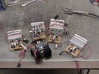
Experiment, have fun. I've built five of these amps, two stock, one with IRF120s and two with IRFP460s and other changes.
In the ACA, Q2 is not a Constant current source, it looks more like a negative impedance load. Because of the way the Drain of Q1 is coupled to the Gate of Q2 via C2 and the load connection to the junction of R1 and R3, an increase in current by Q1 results in a reduction of current in Q2. Q3 regulates the voltage between the Source of Q2 and the Drain of Q1. If the current in R3 goes up, the current in R1 must go down. The voltage across Q2 goes up but the current goes down. That's a negative impedance.
In the selection of values for R1-4, Nelson has introduced a nonlinearity which gives the ACA it's pleasing sound. Replacing Q2 with a CCS would improve linearity but the quiescent current would need to be increased. There would still be some nonlinearity because Q1 is operated in a nonlinear region. Simply increasing Q1's current reduces distortion. The bridge configuration really cuts the distortion numbers due to increased current and so called even order harmonic "cancellation" (I think that term is misleading).
Experiment, have fun. I've built five of these amps, two stock, one with IRF120s and two with IRFP460s and other changes.
Attachments
- Home
- Amplifiers
- Pass Labs
- Amp Camp Amp - ACA