That won't work as intended. You are picking off a signal from inside the feedback loop where it is distorted to compensate for the non-linearity of Q1, the signal level is reduced by feedback so the level will be wrong and there will be high frequency emphisis caused by Q1's gate capacitance.
Good observation, something I hadn't considered.
Back to the drawing table...
jan
Good observation, something I hadn't considered.
Let's take a look. In an exercise that served me well when I was thinking
about the "SuperSymmetric" design, let's imagine that a small positive
distortion spike occurs at the output of the first amplifier in the balanced
system.
This spike will also be found to be positive at the Gate of the input
transistor due to the feedback loop. This will create a negative spike at
the Drain of that input device, which is the source of the signal driving
the other side of the balanced amplifier. That spike will appear as a
positive spike on its output. Now both sides of the balanced amplifier
have a positive spike.
and Voila!
Q1 is not very linear without some source degeneration. Search this thread for some of my earlier posts. Because of the global feedback, the signal at the gate of Q4 is somewhat distorted in an attempt to correct for Q1's non-linearity. The non-linearity increases slightly above about 5kHz because of the gate capacitance of Q1. This further distorts the drain current of Q4.
A simple way to generate the "other" phase would be to replace R11 with a 68.1K resistor and connect the input to the output of the first side. The gain won't be a prefect -1.000 because the open loop gain of the ACA is fairly low. The value will have to be decreased by several precent. I was taught the math sometime in the 70's, at this point I just remember the general concept.
A simple way to generate the "other" phase would be to replace R11 with a 68.1K resistor and connect the input to the output of the first side. The gain won't be a prefect -1.000 because the open loop gain of the ACA is fairly low. The value will have to be decreased by several precent. I was taught the math sometime in the 70's, at this point I just remember the general concept.
Loudthud: You are absolutely correct. Thank you for catching my error. You saved my hide! I failed to pay attention to the origin of the feedback loop. Fortunately, two possible options still remain. I'll post tomorrow the refined diagram of both. Here is the heads-up:
Loudthud: I hope that you agree with these two possible options. Please confirm. Thank you.
- Keep the output blocking capacitor in both ACA amps. Connect the loudspeaker leads between the existing output ports. Thus, both output capacitors are in the path of the output current flowing through the loudspeaker.
- Keep the output blocking capacitor in both ACA amps. Adjust the ouput DC voltage at each output to 10.0 VDC with the P1 potentiometers as recommended in the article by Mr. Pass. Connect one loudspeaker terminal to the output node of the upper ACA at the positive lead of its output blocking capacitor. Connect the other end of the loudspeaker to the ouput node of the bottom ACA at the positive lead of its ouput blocking capacitor. This arrangement bypasses both ouput capacitors from the path of the output current through the loudspeaker, and simultaneously preserves the original operation of the feedback loop and the front end.
As promised, the refined schematic/diagram which is attendant to this post is attached as bridgeACA2.pdf. Here are my general comments:
- I show the passive approach of using a transformer [JENSEN as before] to generate the out of phase input signals to the ACAs. The diagram at the output of the ACAs equally applies to using the approaches posted earlier by Mega-amp and janneman.
- I added detail to the input and output circuit of the upper ACA from the published schematic in the article by Mr. Pass. This detail is not shown for the lower ACA. The purpose of showing this detail is to emphasize that this proposed diagram does not have errors which otherwise will upset the operation of the amp and the transformer [magnetize it].
- The loudspeaker needs to be connected to either output ports [A and A'] or [B and B'].
- The output ports A and A' show that the two output capacitors are in series with each other and with the loudspeaker. Their equivalent capacitance is 1650 uF which maybe detrimental to the low end performance. It is also possible that certain DIYers may object to the potential impact on sound by these capacitors.
- The possible detriment which is associated with ports A and A' disappears when using ports B and B' instead. The capacitors are still present; but the power output signal bypasses them completely. But; one must protect both amps and the loudspeaker with the shown fuses should the output ports B and B' be [inadvertently] shorted to the power supply common/ground
- The principle purpose of bridging is to quadruple output power. But, each ACA [as is] has the ability to put out only 1 Amp and may be unable to generate the needed 2 A [each] for the bridge.
- The intrisic output impedance of each ACA maybe 2 Ohms [for example]. So in the bridge configuration, the loudspeaker is effectively in series with 4 Ohms resistive. This added resistance may rob it from accoustic output; an efficiency issue.
- The concern about harmonic distortion which is disturbed in the bridge, and which is beneficial by design in the solo use of ACA.
Attachments
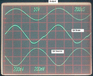
I'm not sure what Nelson was getting at exactly. Here are a few measurements I took and a scope photo where you can see the distortion at Q4's Drain.
Distortion 1kHz 1 Watt @ 8 ohms
Output 0.79%
Q4 Source 3.46%
Q4 Drain 6.04%
Distortion 1kHz 3 Watt @ 8 ohms
Output 1.63%
Q4 Source 6.55%
Q4 Drain 12.8%
Note that the generator amplitude was 963mV RMS. Signal at Q4 Source is about 140mV RMS.
Distortion 1kHz 1 Watt @ 8 ohms
Output 0.79%
Q4 Source 3.46%
Q4 Drain 6.04%
Distortion 1kHz 3 Watt @ 8 ohms
Output 1.63%
Q4 Source 6.55%
Q4 Drain 12.8%
Note that the generator amplitude was 963mV RMS. Signal at Q4 Source is about 140mV RMS.
Attachments
As promised, the refined schematic/diagram which is attendant to this post is attached as bridgeACA2.pdf. Here are my general comments:
Loudthud raised multiple and specific concerns regarding bridging ACAs; which the DYIer needs to seriously consider in this briging endeavor:
- I show the passive approach of using a transformer [JENSEN as before] to generate the out of phase input signals to the ACAs. The diagram at the output of the ACAs equally applies to using the approaches posted earlier by Mega-amp and janneman.
- I added detail to the input and output circuit of the upper ACA from the published schematic in the article by Mr. Pass. This detail is not shown for the lower ACA. The purpose of showing this detail is to emphasize that this proposed diagram does not have errors which otherwise will upset the operation of the amp and the transformer [magnetize it].
- The loudspeaker needs to be connected to either output ports [A and A'] or [B and B'].
- The output ports A and A' show that the two output capacitors are in series with each other and with the loudspeaker. Their equivalent capacitance is 1650 uF which maybe detrimental to the low end performance. It is also possible that certain DIYers may object to the potential impact on sound by these capacitors.
- The possible detriment which is associated with ports A and A' disappears when using ports B and B' instead. The capacitors are still present; but the power output signal bypasses them completely. But; one must protect both amps and the loudspeaker with the shown fuses should the output ports B and B' be [inadvertently] shorted to the power supply common/ground
- The principle purpose of bridging is to quadruple output power. But, each ACA [as is] has the ability to put out only 1 Amp and may be unable to generate the needed 2 A [each] for the bridge.
- The intrisic output impedance of each ACA maybe 2 Ohms [for example]. So in the bridge configuration, the loudspeaker is effectively in series with 4 Ohms resistive. This added resistance may rob it from accoustic output; an efficiency issue.
- The concern about harmonic distortion which is disturbed in the bridge, and which is beneficial by design in the solo use of ACA.
A few comments: if you carefully balance the bridged output for equal DC (half supply) there is no longer a need for output caps. If you want to play it safe, a single output cap on one side will do.
The bias current should be increased in the bridged mode of course. You don't get anything for free: quadruple the output power will also mean quadruple the (class A) dissipation and that results from a) double the bias current and b) two amplifiers.
@Loudthud: what was the circuit in the '170 drain lead used for your distortion measurements? Did you measure against earth?
jan
Loudthud:It seems to me that loop feedback is contaminating the intrinsic performance of Q4 [in janneman's schematic] which maybe pristine without it. What are the distortion properties at the source and drain of Q4 without loop feedback by comparison? How great is the performance of Q4?I'm not sure what Nelson was getting at exactly. Here are a few measurements I took and a scope photo where you can see the distortion at Q4's Drain.
Distortion 1kHz 1 Watt @ 8 ohms
Output 0.79%
Q4 Source 3.46%
Q4 Drain 6.04%
Distortion 1kHz 3 Watt @ 8 ohms
Output 1.63%
Q4 Source 6.55%
Q4 Drain 12.8%
Note that the generator amplitude was 963mV RMS. Signal at Q4 Source is about 140mV RMS.
@Loudthud: what was the circuit in the '170 drain lead used for your distortion measurements? Did you measure against earth?
Yes. The 100K input impedance of my Audio Precision System 1 is capacitor coupled. I just left the ground connected and moved the hot lead to different points. To double check, I connected the System 1 differentially across the 1K Drain resistor and there was very little difference in the distortion reading. In the scope photo the output is DC coupled before the output capicitor, the other two traces are AC coupled.
I'm using a linear bench power supply. My shop is about 2 miles from a 50KW AM radio station. At times it gets into things, the analyzer seems to need a ground wire clipped to the circuit under test. There is a 5 Megawatt TV transmitter about 300 yards from the shop, but I never noticed any interference from it despite using a 1 GHz scope.
Loudthud:It seems to me that loop feedback is contaminating the intrinsic performance of Q4 [in janneman's schematic] which maybe pristine without it. What are the distortion properties at the source and drain of Q4 without loop feedback by comparison? How great is the performance of Q4?
Yes, inside the loop distortion can increase quite a bit. The non-linearity of Q1 and it's input capacitance create distortion that the feedback tries to correct. Feeding a square wave to the input you see a couple of hunderd precent overshoot at the Source of Q4 and a great deal more at the Drain. The output looks like an ideal bandwidth limited square wave.
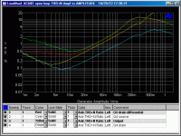
I'll try to plot some meaningfull openloop distortion graphs.
Thank you Loudthud.Yes, inside the loop distortion can increase quite a bit. The non-linearity of Q1 and it's input capacitance create distortion that the feedback tries to correct. Feeding a square wave to the input you see a couple of hunderd precent overshoot at the Source of Q4 and a great deal more at the Drain. The output looks like an ideal bandwidth limited square wave.
I'll try to plot some meaningfull openloop distortion graphs.
Thank you jan for your comments. I am glad that we agree on the options which can manage the mating of the outputs of 2 ACAs in bridge configuration.A few comments: if you carefully balance the bridged output for equal DC (half supply) there is no longer a need for output caps. If you want to play it safe, a single output cap on one side will do.
The bias current should be increased in the bridged mode of course. You don't get anything for free: quadruple the output power will also mean quadruple the (class A) dissipation and that results from a) double the bias current and b) two amplifiers.
@Loudthud: what was the circuit in the '170 drain lead used for your distortion measurements? Did you measure against earth?
jan
This question posed by DIYers still hangs: Can I bridge 2 ACAs? I am afraid the answer is no for the following reasons:
- The power supply is undersized.
- The heat sink is undersized.
- Doubling the idle bias needs specific modifications from Mr. Pass and/or his appointee.
Yes, inside the loop distortion can increase quite a bit. The non-linearity of Q1 and it's input capacitance create distortion that the feedback tries to correct. Feeding a square wave to the input you see a couple of hunderd precent overshoot at the Source of Q4 and a great deal more at the Drain. The output looks like an ideal bandwidth limited square wave.
I'll try to plot some meaningfull openloop distortion graphs.
Well the overshoot is not about distortion, it is about gain-bandwidth, a different thing. The real test is to band-limit the square wave to say a 1st order 20kHz, then look at eventual overshoot.
You can always cause overshoot in any feedback amp if you make the rise/fall time high enough, but that's not really saying anything about the performance with music.
The reason for my question above is that I noticed that the distortion on the drain is almost double that on the source, which is curious.
jan
Thank you jan for your comments. I am glad that we agree on the options which can manage the mating of the outputs of 2 ACAs in bridge configuration.
This question posed by DIYers still hangs: Can I bridge 2 ACAs? I am afraid the answer is no for the following reasons:
Maybe others have a different verdict!
- The power supply is undersized.
- The heat sink is undersized.
- Doubling the idle bias needs specific modifications from Mr. Pass and/or his appointee.
The power supply is OK, needs no change, if it can supply enough current, or you use one with more current.
Increase heat sink, yes.
The bias current can be increased easily by lowering the 4 resistors that make up the bias sensing from say 0.68 to 0.39 ohms or so.
But I agree, it really becomes a different amp.
Just an idea I had...
jan
I agree jan. The DIYer will need a specific set of guidelines and a procedure to transform the current ACA to a bridgeable amp. Maybe Mr. Pass will create an ACA Turbo which can be bridged with no further DIYer modification of its circuit.The power supply is OK, needs no change, if it can supply enough current, or you use one with more current.
Increase heat sink, yes.
The bias current can be increased easily by lowering the 4 resistors that make up the bias sensing from say 0.68 to 0.39 ohms or so.
But I agree, it really becomes a different amp.
Just an idea I had...
jan
Well the overshoot is not about distortion, it is about gain-bandwidth, a different thing. The real test is to band-limit the square wave to say a 1st order 20kHz, then look at eventual overshoot.
You can always cause overshoot in any feedback amp if you make the rise/fall time high enough, but that's not really saying anything about the performance with music.
The reason for my question above is that I noticed that the distortion on the drain is almost double that on the source, which is curious.
jan
Voltage at the drain in the split load phase inverter (an analog of the drain current) depends on the total impedance at the source which includes the gate of Q1 and it's gate stopper. The point of the overshoot being that Q1 is a substantial load. I tried the ACA using IRFP460's which have a Ciss over 4000pF. The results were terrible even with 3 Q4's in parallel and R9 at 330 ohms. Obvious distortion on high amplitude outputs even at 1kHz. The non-linearity of the capacitance was evident when Q1's drain voltage dips below it's gate voltage.
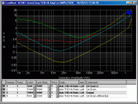
Getting the analyer to plot distortion vs generator amplitude was not straight forward, it likes to plot against the analyzer amplitude. I think I got it right, but the graphs have some surprises. Q4's drain voltage is plotted single ended to ground and differentially across the 1K resistor. I didn't install the decoupling network that Jan used, but there is a 100uF cap bypassing the 19V right near Q4.
Attachments
- Home
- Amplifiers
- Pass Labs
- Amp Camp Amp - ACA


