Buildind dual mono
I wanted build this amp into one case: my concern is that in this way the GND signal of the 2 channel will be in common as there is connection between the pcb GND and the dissipator. Shall I have to isolate the PCBs from their dissipators or there is no problem? Thanks in advance
I wanted build this amp into one case: my concern is that in this way the GND signal of the 2 channel will be in common as there is connection between the pcb GND and the dissipator. Shall I have to isolate the PCBs from their dissipators or there is no problem? Thanks in advance
Yes, thank you.
Do you mean the article?
It's here:
http://www.diyaudio.com/forums/diyaudio-com-articles/158899-arpeggio-loudspeaker.html
I wanted build this amp into one case: my concern is that in this way the GND signal of the 2 channel will be in common as there is connection between the pcb GND and the dissipator. Shall I have to isolate the PCBs from their dissipators or there is no problem? Thanks in advance
Please, help me, no one knows if for stereo configuration the PCB GND must be isolated from the dissipator? (this because in one case there will be connection between the two dissipator)?
Mr. Brock. I published the following application to lower a high output impedance [e.g. 8 Ohms] of a voltage source amplifier [an amplifier with special performance] to that of an ideal voltage source amplifier [Zo<0.1 Ohms] . My intent is to enable this special amplifier to drive almost any available loudpeaker, and thus broaden its scope of use. This study is found in posts # 27, 28 and 29 of the Thread which is entitled "Compound Power Amplifiers" in the Pass Labs Forum. Please consult the attached schematic to get an initial impression of the subject. In this schematic, an 8 Ohms power resistor was inserted in series with the output port of the Left channel of a Threshold S/150 stereo amplifier to simulate this special amplifier; possibly ACA#1. The Right channel of S/150 acted as the second component of the compound amplifier. The compound power amplifier [CPA] has the output impedance of the Right channel of S/150 [published < 0.1 Ohms]. The output power of the CPA is the same as, and is totally attributed to this "modified" Left channel of S/150 of simulated special performance. The Right channel does not contribute output power to the loudspeaker. Instead, it acts as a dynamic output current sink when the impedance of the loudspeaker in use exceeds a preset value as a function of frequency. Thus, the special amplifier has been converted to a CPA which is an ideal voltage source amplifier.Ah ha, I missed that post, thanks for pointing it out. It seems then that matching the output impedance to a speaker like the arpeggio is a bit more complicated than I previously believed. I'll have to put some more thought into this one.
I'll be glad to engage you and others on the possible compounding of ACA#1 in upcoming posts of this thread.
Attachments
How are everyone's builds going?
I'm getting things in place to build the amp now. Just ordering power supplies.
Seems the more advanced among us are planning modifications/alterations before some noobs may have completed the build - could we have a new thread for builders questions & completed builds, or maybe another for mods to the ACA so the learners don't get blown away?
I know how you guys like to mess with Mr 's designs and, hopefully the ACA will set more of us on that path with confidence
I'm getting things in place to build the amp now. Just ordering power supplies.
Seems the more advanced among us are planning modifications/alterations before some noobs may have completed the build - could we have a new thread for builders questions & completed builds, or maybe another for mods to the ACA so the learners don't get blown away?
I know how you guys like to mess with Mr
's designs and, hopefully the ACA will set more of us on that path with confidenceSeems the more advanced among us are planning modifications/alterations before some noobs may have completed the build - could we have a new thread for builders questions & completed builds, or maybe another for mods to the ACA so the learners don't get blown away?
I wouldn't mind seeing the questions in the build guide thread. It would also prompt me to update it if something is unclear or incorrect.
Amp Camp Complete!
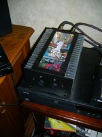
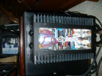
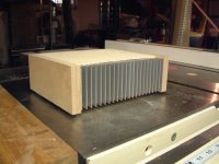
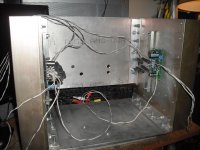
I completed my Amp Camp #1 from the DiyAudio Kit! Here you have some pics.
It is stereo version case, made from scrap aluminium; the top is plexyglass.
The channels are completely separate, isolating the pcb GND from the dissipator.
The sound is AMAZING. I didn't think it would have played so well, the sound comes alive at very low levels and is full and rich at any frequencies.
I don't know if it is because of my setup (Arcam CD73, Kingrex Preamp, Klipsch RF82) but from my first listening I noticed surprisingly bass response!
I will do more listening sessions and I let you know in a few days time.
The only issue I have is a turn off thump one the loudspeakers, but I'll investigate later.
This is my first class A amp and I recommend it to everyone because it has excellent quality/cost ratio!
Attachments
Thank you JRKO for your post. Fortunately, I did not suggest in my previous post to modify ACA#1. It is a special and perfect amp as designed, and thus untouchable. I am 100% for assembling it and using it exactly as recommended with the Arpeggio loudspeaker etc. After doing all this, then the DIYer may consider my suggestion to expand or diversify the use of ACA#1 in a compound setup which maybe a transient experiment or a permanent integration.How are everyone's builds going?
I'm getting things in place to build the amp now. Just ordering power supplies.
Seems the more advanced among us are planning modifications/alterations before some noobs may have completed the build - could we have a new thread for builders questions & completed builds, or maybe another for mods to the ACA so the learners don't get blown away?
I know how you guys like to mess with Mr
I tried a little experiment. I put a jumper (alligator clips) across the 10k (R11) feedback resistor shorting it out. I am not sure what the input impedance becomes (I think it goes way down), but the dac was able to drive it. The result was a lot more gain. The base output went up and the top end went down. It sounded a lot more like my SE 300B but that’s not to say I prefer it. However it’s worth trying just to see the effect. But you have to be careful to make sure your jumping out the right resistor otherwise you could blow your amp check it twice.
Leve
Leve
The only issue I have is a turn off thump one the loudspeakers, but I'll investigate later.
You could use a double pole power switch and just disconnect the speaker when the amp is powerered off. There is no turn-on thump because C2 charges up slowly thus the current ramps up slowly giving C1 time to charge up.
I tried a little experiment. I put a jumper (alligator clips) across the 10k (R11) feedback resistor shorting it out. I am not sure what the input impedance becomes (I think it goes way down), but the dac was able to drive it. The result was a lot more gain. The base output went up and the top end went down. It sounded a lot more like my SE 300B but that’s not to say I prefer it. However it’s worth trying just to see the effect. But you have to be careful to make sure your jumping out the right resistor otherwise you could blow your amp check it twice.
Leve
You can come pretty close to the closed loop distortion numbers without feedback by adding a resistor in the source of Q1 and adjusting the R1-R2 / R3-R4 ratio. Search for my previous posts in this thread. Frequency response and high frequency distortion may suffer. Perhaps paralleling Q4 and reducing R9 would help in that area. I tried a bigger Q1 and the results were bad.
It seems to me that Nelson choose the R1-R2 / R3-R4 ratio to create 2nd harmonic distortion for a more pleasing sound. I'm not very good at making those kind of judgements, try it and tell me what you think.
- Home
- Amplifiers
- Pass Labs
- Amp Camp Amp - ACA