We're still adding up the cost, and buying stuff like anti-stat bags and a box to keep the parts safe in transit. But since there aren't that many parts we're keeping them high quality. The caps, pot and active devices are as mentioned in Nelson Pass' article. The smaller resistors will be upgraded to Vishay-Dale metal films. There will be nice switches, speaker terminals, power jacks, LED's, grease, insulators, bolts, washers, even wire! Drilled and tapped heatsinks will be available separately.
Our goal is you get all that's required to sit down and make a functioning amp!
Our goal is you get all that's required to sit down and make a functioning amp!
Last edited:
Our goal is you get all that's required to sit down and make a functioning amp!
PERFECT!
")
I'm looking foward to get a stereo kit soon, when it's available in the shop!

regards,
Matthias
Somewhere along the line, someone pounded into my head the idea that you should make a circuit as linear as possible, then apply feedback. To that end, and in view of my previous post #274, I have been playing with the R1/R2 and R3/R4 resistors.
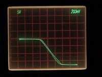
It looks like R3/R4 wants to be 0.82 ohms and R1/R2 0.15 ohms. This cuts the quiescent current so I added a pot with a series resistor between base and emitter of Q4. I arrived at these values by tweeking the open loop amp, first on the X-Y display, then at 1 watt, 1kHz using the distortion analyzer. If you don't have those resistors available (I didn't) use 1 ohm in parallel with 4.7 ohms for R3/R4 and a 0.22 in parallel with 0.47 for R1/R2. The extra resistor to restore the current turns out to be about 1K.
I had a 0.22 ohm resistor in series with Q1's source, later I shorted it out and it made almost no difference in the distortion numbers. I also adjusted the quiescent current, it had been running about 1.3 amps with the stock circuit, there was a slight decrease in distortion when it was lowered to 1 amp.
What I don't understand is now the distortion rises below 100mW. The stock circuit keeps falling to around 1mW. Am I picking up noise?
Attachments
We're still adding up the cost, and buying stuff like anti-stat bags and a box to keep the parts safe in transit. But since there aren't that many parts we're keeping them high quality. The caps, pot and active devices are as mentioned in Nelson Pass' article. The smaller resistors will be upgraded to Vishay-Dale metal films. There will be nice switches, speaker terminals, power jacks, LED's, grease, insulators, bolts, washers, even wire! Drilled and tapped heatsinks will be available separately.
Our goal is you get all that's required to sit down and make a functioning amp!
I am going to build a few of these suckers to go with my B5
You can never have too many amps
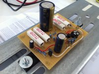
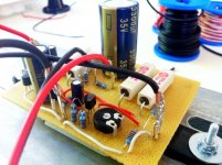
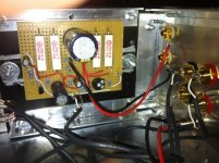
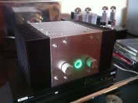
I've given a try on building a stereo version of the ACA with a high-end preAmp (in form of a 22k pot an a source selector switch ).
Really a nice device, although, as it was my first amp of this kind, gave me a bit of a heart-burn watching the Q1 drain voltage on the first switch on - first nothing, then 15v, then back to 10v after 15 secs...
Sadly, I own it no more - my 8-yr-old daughter has it now. Maybe I build myself another one, still have a fitting heat sink...
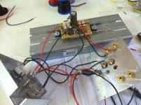
On the pics you see first the later right channel on a "test" heat sink, the first test run, then the left channel already on the final heat sink, and the completed assembly (and yes, that's a set of EL34s in the background)
).Really a nice device, although, as it was my first amp of this kind, gave me a bit of a heart-burn watching the Q1 drain voltage on the first switch on - first nothing, then 15v, then back to 10v after 15 secs...
Sadly, I own it no more - my 8-yr-old daughter has it now. Maybe I build myself another one, still have a fitting heat sink...
On the pics you see first the later right channel on a "test" heat sink, the first test run, then the left channel already on the final heat sink, and the completed assembly (and yes, that's a set of EL34s in the background
)Attachments
...... my 8-yr-old daughter has it now........
she's having right spirit!

I've given a try on building a stereo version of the ACA with a high-end preAmp (in form of a 22k pot an a source selector switch
Really a nice device, although, as it was my first amp of this kind, gave me a bit of a heart-burn watching the Q1 drain voltage on the first switch on - first nothing, then 15v, then back to 10v after 15 secs...
Sadly, I own it no more - my 8-yr-old daughter has it now. Maybe I build myself another one, still have a fitting heat sink...
On the pics you see first the later right channel on a "test" heat sink, the first test run, then the left channel already on the final heat sink, and the completed assembly (and yes, that's a set of EL34s in the background
nice
Any comment on what it sounds like? Can someone compare it to something in the Firstwatt line or anything? How does it sound compared to that EL34? I’m starting to take this as a bad sign that none of the people who built it have anything to say about how it sounds.
You gave it away almost immediately after having built it you say?
You gave it away almost immediately after having built it you say?
update
built my second channel and it has now played in my system for a few weeks. I have not compared it directly to my f5 or other amps i have but with 2sk369 as jfet and 2n4401 as bjt, i think i could live with it for a long time and i dont feel the need to put back the f5 modules. Now if only sic power jfet were cheaper...
p.s.; i have lowther dx3
I will give you a review.
If you are a newbie, then hearing your newly built amplifier will be the
second greatest experience of your life.
If you have had a child, then it would be the third.
If you haven't had the first greatest experience, then perhaps this would
be it after all.
If you are a newbie, then hearing your newly built amplifier will be the
second greatest experience of your life.
If you have had a child, then it would be the third.
If you haven't had the first greatest experience, then perhaps this would
be it after all.
I've heard quite a few of them at Amp Camp, but only for a few minutes each. Then the day after Amp Camp, five of us listened to a pair running through BOFU BIB speakers for about an hour. Couldn't tear myself away. With the correct speaker they give you chills. A bit warmer and sweeter than an F-5 IMHO, as you'd expect. Addicting to listen to: more than you'd expect
Last edited:
C3 &C4 are Silmic II's, C1 & C2 are Panasonics. This is like the originals, and what we all listened to.
C1 footprint on the board will accommodate 25mm dia. caps with snap-in lead spacing of 10mm.
C2 is 10mm dia. 16v with 5mm lead spacing.
Silmic II's come in a maximum size of 1000uF I believe, so they'd have to be mounted off the board as you'd need 3 or 4 for C1
Still that can be done in a very tidy manner as the C1 holes are right on the edge of the board. Whether it will make a difference, I don't know, but
this will be the first time I'll be able to compare. Since the amps are reasonably inexpensive. I'll finally have 2 pairs of monoblocks so I can compare variations and actually have a real opinion on this cap stuff and other parts substitutions
Last edited:
Sadly, I own it no more - my 8-yr-old daughter has it now
My 8 year old nephew soldered a pair up and assembled the chassis' with his dad standing by.
- Home
- Amplifiers
- Pass Labs
- Amp Camp Amp - ACA