Do you an estimate of price per kit, and its shippment to the East coast ?Ok, I've got the parts kits all bundled up and I'm really proud of them. They'll have everything required to make a functioning amp, including wire! Jason, diyFounder, was in town and helped out on some of the packaging. Of course we forgot a few things and are ordering them. The boards should arrive soon, I hope this week and will be added to the kits. Tragically I'm leaving town in a couple of days until the 14th of August. So within a month kids, can't do anything until the boards arrive.
Mark
Just got word that the boards will be sent by air tomorrow. But I won't be able to finish the kits before I leave town..
Safe travels Variac.
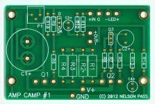
Thanks, I'll be leaving tomorrow, but was here to get the package from the Fed Ex dude. The PCB's look great! and the kits are really close to ready. I'll be back on the 15th so can put it all together then and send them off to the store. So it looks like a solid 2-3 weeks at most
Here;s a photo of the finished boards:
Here;s a photo of the finished boards:
Attachments

I still see it strange why is the PCB with errors is posted here (or did i missed the explanation somewhere?):
http://www.diyaudio.com/forums/diyaudio-com-articles/214808-amp-camp-amp-1-a.html
While this new PCB matches the ones used at the meeting:
http://www.diyaudio.com/media/files/articles/ampcamp1/photo3.png
http://www.diyaudio.com/forums/diyaudio-com-articles/214808-amp-camp-amp-1-a.html
While this new PCB matches the ones used at the meeting:
http://www.diyaudio.com/media/files/articles/ampcamp1/photo3.png
I haven't tried bridge mode yet, but I built a second channel with IRFP460s. Seems like the distortion is lower but my AP System 1 is on the fritz. I did notice that the DC level control does not track the power supply. It keeps the level the same as the supply goes from 20 to 30V. I plan to try a P-channel JFET (or PNP transistor) on the input like knutn tried on the PLH: http://www.diyaudio.com/forums/pass-labs/203915-nostalgia-all-fet-jlh-plh-class-amplifier.html
Please see thread #632 in the topic F6 amplifier for ideas.Has anyone tried bridging a pair of ACAs?
I did notice that the DC level control does not track the power supply. It keeps the level the same as the supply goes from 20 to 30V.
I plan to try a P-channel JFET (or PNP transistor) on the input like knutn tried on the PLH.
This is to be expected. The DC servo on this amp works like the Vbe bias transistor on a regular follower amp. That is to say P1 makesa resistive divider between output and ground. The middle point is referenced to the gate of Q1. At start-up the bottom mosfet is not conducting, but the current source (top mosfet) will start flowing down current. This will cause the output before the dc blocking cap to rise. When it rises high enough it will cause Q4 and in turn Q1 to conduct bringing the voltage down, because P1 takes the before DC blocking output voltage divides it by some percent and delivers it to the gate of Q4. When it starts to conduct is determined by where P1 is set and the Vgs threshold voltages of Q4 and Q1 summed. Increasing the rail voltage has no effect, you have to readjust.
Mr. Pass told me about calculating output impedance so I am in turn passing what I know…
You can’t simply plug a P-channel JFET . I did propose a modification that would let you use a P-channel jfet here:
This would change the feedback to source feedback. The whole amp topology changes to non-inverting. It seems ok in simulation. Such an amp would more or less adjust to rail voltage changes, but again it is a totally different amp. The schematic looking similar is a trick of the eye. Note the jfet has changed from N to P type and it has been flipped with the drain now pointing to Q1 instead of the source. It might be better to use a pot here to adjust the before dc offset to (v+)/2 .
I am also curious about J175 in a source feedback type topology, because it can be used to drive power JFETs which cannot be simply dropped into the current amp camp.
Last edited:
The topology I use is much like the original single rail JLH were emitter (or source) current for the input transistor (I call Q5) comes from the feedback loop. The problem is that the impedance at the gate of Q1 needs to be low and that requires lots of current, 5 to 10mA. To lower the impedance of the feedback loop requires a bigger than I would like capacitor in the ground leg of the feedback network. So I was going to keep Q4 in the circuit with a resistor of maybe 10K to ground on the gate and drive that with about 300uA from the added input device Q5.
I built an amp with the input device Q5 driving the MOSFET Q1 directly. I had to add a current source from the positive rail (much like later JLH versions) to keep the feedback loop impedance up. Results were mixed. I tried making a dual rail version but that is problematic without a diff pair on the input. I want to keep things simple with a single ended input stage.
I built an amp with the input device Q5 driving the MOSFET Q1 directly. I had to add a current source from the positive rail (much like later JLH versions) to keep the feedback loop impedance up. Results were mixed. I tried making a dual rail version but that is problematic without a diff pair on the input. I want to keep things simple with a single ended input stage.
Has anyone tried bridging a pair of ACAs?
I did try driving a 4 ohm load. The stock ACA is a little weak and distortion is higher. I increased the current by adding one additional resistor in parallel R1/R2 and R3/R4. That got the distortion back to where the stock version measures with an 8 ohm load. Naturally the heat sink got hotter. If you are satisified with 5 watts, reduce the supply to 13V and the dissipation is about the same.
- Home
- Amplifiers
- Pass Labs
- Amp Camp Amp - ACA