Hello i'm new here (first post) and i like diy, in the past i have built a gainclone from a kit, some CMoy for my headphones and a set of two way speakers with monacor drivers.
It's some time that i'm lurking on threads about project by Mr.Pass.
I started dreaming about building a F5 and a B1 but i'd like to do something simpler first.
Will the pcb in the store be a kit or a bare pcb?
Where can i find 3w resistors in EU?
Are the heatsink 3PD02200 from hifi2000/modushp ok ?
Thank you all, and a really big thank to Mr.Pass and Variac for that amp.
p.s. sorry for my english
you'll hardly find anything simpler than F5 on entire forum
regarding Modu heatsinks - give us the link
I know where to look for it , but I'm lazy
I can be lazy , because you asked .......
3W Metal Oxid resistors - look at Mouser ; for questions like this , it's handy when I can see your flag , below your avatar ..... ooops , your nick
regarding Modu heatsinks - give us the link
I know where to look for it , but I'm lazy
I can be lazy , because you asked .......
3W Metal Oxid resistors - look at Mouser ; for questions like this , it's handy when I can see your flag , below your avatar ..... ooops , your nick
The modushop heatsink link is:
modushop.biz
Thank you for the fast answer, i have found 3w resistors on mouser but not the low values requested for the CampAmp.
I am in Italy but i don't know how to "show off" the little flag everyone have near the name.
I'd really like to build a F5 but i'd prefer to "re-enter" diy world starting from something that do not require me to solder a "big and scary" PSU.
yup , 3PD02200 from Modu is good enough for 20W of dissipation
so - one per channel .
regarding your flag - on top of any page you'll find "user CP/your profile" , where you can edit your location
regarding MOX - just go to Google and search for "metal oxide resistor" ........ in Italy
look : - Google Search
so - one per channel .
regarding your flag - on top of any page you'll find "user CP/your profile" , where you can edit your location
regarding MOX - just go to Google and search for "metal oxide resistor" ........ in Italy
look : - Google Search
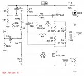
AMP CAMP JLH Nouveau
The similarities to the JLH are in fact extraordinary. Both amps use resistors and semiconductors and the other differences already pointed out. If the amp took its feedback the same way as the JLH did (in fact it’s the bottom half of an F5) the input impedance would go up higher then 50K which would be nice. And the feedback network (gain) would be independent of the preamp’s output impedance. I have simulated this, it does seem to work, clipping comes on a little quicker, but my values may not be ideal. I don’t know how it would change the sonic character of the amp. Unfortunately q4 becomes a P-type Jfet and they are much harder to find. Also I think you could eliminate the DC adjustment pot.
btw, this amp looks pretty similar to JLH 1969
The similarities to the JLH are in fact extraordinary. Both amps use resistors and semiconductors and the other differences already pointed out. If the amp took its feedback the same way as the JLH did (in fact it’s the bottom half of an F5) the input impedance would go up higher then 50K which would be nice. And the feedback network (gain) would be independent of the preamp’s output impedance. I have simulated this, it does seem to work, clipping comes on a little quicker, but my values may not be ideal. I don’t know how it would change the sonic character of the amp. Unfortunately q4 becomes a P-type Jfet and they are much harder to find. Also I think you could eliminate the DC adjustment pot.
Attachments
Will the pcb in the store be a kit or a bare pcb? Are the heatsink 3PD02200 from hifi2000/modushp ok?
We will be offering kits and bare PCBs in the store.
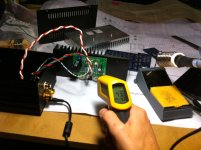
Funny you should ask about the 3PD02200
In my testing, it's typically 20'C above the ambient temperature, plus or minus 2'C. The temperature here in SF is currently 23'C and the max temperature I get anywhere on or near the Mosfets is 43'C.Attachments
What are the functions of R1~R4 besides setting the bias current? Thanks.
I can't tell you what NP was thinking, but I've been working on a variation of the circuit for the last 6 months. The Amp Camp circuit supplies a constant current to Q1 because of the 1000uF cap, C2. My circuit works more like the Aleph current source, the current source forms a negative resistance that improves efficiency. I've been using a 55V rail giving 50W into 4 ohms using a CPU heatsink with fan.
A word of warning to those wanting to try bigger voltages. When the output clips, the MOSFET drive will slam the rails (depending on the amount of feedback). Gate zeners are suggested.
Attachments
I believe the Amp Camp Amp would supply constant current to Q1 without that 1000u in the circuit
It's all those other components that make the constant current function. Mainly Q3 and R1-R4 along with Q2 of coarse, and I guess you gotta have R7 too.
No, Q1 would not maintain a constant current (except in the case where load current is zero). Without C2, consider what happends with a positive going input at [IN]. Current in Q1 increases. This increases the drop across R3, R4. Q3 sees this increase and pulls the gate of Q2 down to reduce the drop across R1, R2 until the drop from the source of Q2 to the drain of Q1 is the same. But the current in Q2 has decreased and Q1's current has increassed. The difference in current goes to the load. With C2 in the circuit, the gate voltage on Q2 is maintained and the current in Q2 does not change. Only Q1's change in current goes to the load.
C2 does bootstrap the gate of Q2 above the rail, otherwise the Q2 could not pull the output higher than +19 minus gate threshold of Q2. R7 supplys current to C2 but does not discharge it significantly when Q2 slams the rail.
Wait a minute. In post #149 you said "The Amp Camp circuit supplies a constant current to Q1 because of the 1000uF cap, C2". I was responding to this point. I read nothing about a load and emplied nothing other than constant current. The cap does not contribute to that function.
Now you are saying "No, Q1 would not maintain a constant current"... If there is 1 major contributor to constant current it would be Q2 not Q1. And ..."(except in the case where load current is zero)."
Exactly the condition I was thinking when you said "The Amp Camp circuit supplies a constant current to Q1 because of the 1000uF cap, C2."
When there is a signal, more than constant current happens, yes. And, Yes, that cap will deffinatly effect the output.
Sorry, the first sentence should read:
No, Q2 would not maintain a constant current (except in the case where load current is zero).
I was responding to what you wrote: "I believe the Amp Camp Amp would supply constant current to Q1 without that 1000u in the circuit"
I thought you were speaking of dynamic currents, not just static conditions. For static conditions C2 is out of the circuit, Q3 sets the current by sensing the voltage across R1. R2, R3, R4 and load current is zero.
My original comment was on the R1, R2, R3, R4 resistors. The way they are connected to the load and the way C2 is connected to the drain of Q1 does something special. I might have to build this thing to figure out exactly how it works. It looks like Q2 is anything but a constant current source with or without C2 in the circuit. If Q1's current suddenly falls to zero, the drop across R3, R4 goes to zero and that increases gate drive to Q2 via C2.... {sound of my head exploding} Not totally unlike the Aleph current source.
Q2 is pushed up and down with signal (thru the cap) while the components I spoke of earlier maintain a constant current across their sensing node. The output connection however, is messing with that constant current sense node such that I don't know if it's actually got anything we can call constant current except in the Source of Q2?
The similarities to the JLH are in fact extraordinary.
If you take a closer look you will see that all the JLH variants (that I've seen)
include a middle stage phase splitter. Here's an early example:
Attachments
As he said
But, it is not a clearcut current source without loop feedback. It is a modulated current source. And, R12 and R11 form the loop feedback that will lower the output impeadance even more.
I fully agree with you as your bolded statement is accurate. So it is a Transconductance Amp [TCA] without loop feedback, and a Voltage Source Amp [VSA] with loop feedback as Zen Mod wrote above. But its output impedance does not approach zero [Damping Factor <5] like a classical VSA [DF >50]. The Camp Amplifier appears to be suspended between these two classifications. It may matter to the loudspeaker's crossover circuit!. The article by Mr. Pass [www.firstwatt.com] suggests that the loudspeaker crossover circuits will be different when driven by a TCA and VSA. So what type of crossover circuit the DIYer best use for a two and multiway drivers?
- Home
- Amplifiers
- Pass Labs
- Amp Camp Amp - ACA