At one time, long ago, I thought I knew how to solder. But than a coworker who was one of the engineering staff taught me more. He was Mil-Spec certified and was able to increase my skills in just a few sessions of tutoring.
One thing used interchangeably and is NOT are the words 'heat' and 'tempreture'.
Heat is what amounts to mass /tempreture. Temp is more of an instantaneous measure. So you can apply a very high temp for a short time without exceeding the 'heat load' of the object. So, you might think of a very large, cold object having more heat than a very small hot object.
I continue to use very thin solder. A eutectic is the maximum point of solubility of one material in another. For example? Silicon is soluble in Aluminum. But only to maybe <2% at any temp. After than is precipitates out. The opposite is misible. This is where 2 substances mix together in ANY proportion. Water and Alcohol, for example.
https://electromet.com/wp-content/uploads/2015/09/Electromet-MILSTD2000a.pdf
Mill Spec standards for soldering. Crazy detailed.
Mill Spec standards for soldering. Crazy detailed.
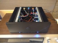
The pinnacle of issues might be what occurred at the very end. I was re-tightening all chassis screws when I snapped the head off a screw holding bracket onto heat sink. Anybody got an extra heatsink, ha! I have the capacity to over tighten like no other. I could leave it. But I would bet that I take that side apart and drill out the remaining shaft.
Your heatsink might not need to be replaced. I suggest you don’t bother removing the snapped bolt. Drill a new hole at least one centimeter away. You,ll have to tap the new hole for threads, but you d have to do that anyway.
Hi guys,
I'm just finishing up my ACA build, and I've got a few issues. No sound out of one channel, but I think that is due to a solder bridge between R2 and R4 or a cold solder joint somewhere.
A weird thing happens with the channel that does work though. When I plug in the power supply with the switch OFF, both LED's are unlit. When I turn the amp ON, both LED's light up, but when I turn the amp OFF again, the LED in the working channel stays lit. I have to unplug the power supply to make it go out. Any idea what might be causing that?
I also can't get a reading on either of the MOSFETs for biasing, but that could be my DMM. It's really hard to probe the center MOSFET leg.
First step is to prove your DMM is working or not. Measure the output from the power supply or some batteries maybe. Compare to what you expect.
Not sure how one LED can remain lit, if the power switch (which supplies +ve to both sides) is open? It suggests you have a wiring error or poor connection somewhere. Does it continue to produce sound as well as having the LED lit?
Does the LED go off if you leave it for a couple of minutes?
Measure the voltage at V+ (from GND) in the 'faulty' condition. What do you read on both sides?
R2 and R4 are joined together at the centre by the way.
Please post some good pictures of your build - boards and wiring so we can help any further.
Alan
Your heatsink might not need to be replaced. I suggest you don’t bother removing the snapped bolt. Drill a new hole at least one centimeter away. You,ll have to tap the new hole for threads, but you d have to do that anyway.
Best Screw Extractor Set Reviews - Pull Out Broken Screws & Bolts Easily
If you do want to extract the old screw, you could get an extractor.
Another option that I've done myself, it's to drill and tap the same hole. Can be tricky but another way of skinning the cat.
amp camp sounds great
Hi,
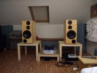
A few months ago I finished my ACA 1.6. It sounds fantastic, smooth, non fatiguing, nice highs and mids. But lacking bass tightness on my speakers (8ohm 88db speakers), but normal since it is only 8watt. My Marantz pm6006 sounds a bit harsh compared to it, I prefer the ACA.
I will be building a M2X soon, still collecting the parts.
It was straight forward to put together, took me 12 hours in total. Biased at 11.6v and 12.1v, so mission succeeded.
It is definitely a keeper, also it dissipates 40watt of heat vs the 160watt of heat of the m2x, so great for the hot summers.
And thanks for Nelson Pass for designing it and diyaudiostore for making the kit available.
Hi,
A few months ago I finished my ACA 1.6. It sounds fantastic, smooth, non fatiguing, nice highs and mids. But lacking bass tightness on my speakers (8ohm 88db speakers), but normal since it is only 8watt. My Marantz pm6006 sounds a bit harsh compared to it, I prefer the ACA.
I will be building a M2X soon, still collecting the parts.
It was straight forward to put together, took me 12 hours in total. Biased at 11.6v and 12.1v, so mission succeeded.
It is definitely a keeper, also it dissipates 40watt of heat vs the 160watt of heat of the m2x, so great for the hot summers.
And thanks for Nelson Pass for designing it and diyaudiostore for making the kit available.
Attachments
Last edited:
Hi,
A few months ago I finished my ACA 1.6. It sounds fantastic, smooth, non fatiguing, nice highs and mids. But lacking bass tightness on my speakers (8ohm 88db speakers), but normal since it is only 8watt. My Marantz pm6006 sounds a bit harsh compared to it, I prefer the ACA.
I will be building a M2X soon, still collecting the parts.
It was straight forward to put together, took me 12 hours in total. Biased at 11.6v and 12.1v, so mission succeeded.
It is definitely a keeper, also it dissipates 40watt of heat vs the 160watt of heat of the m2x, so great for the hot summers.
And thanks for Nelson Pass for designing it and diyaudiostore for making the kit available.
One thing to think about is building a second one and run in monoblock mode (that's what I did with a balance pre up front). I'd expect that you'll find the bass delivery better served if you went that way. Lovely amp even so. Elegance in simplicity.
") (Which in no way diminishes bridged ACAs)
(Which in no way diminishes bridged ACAs)First step is to prove your DMM is working or not. Measure the output from the power supply or some batteries maybe. Compare to what you expect.
Not sure how one LED can remain lit, if the power switch (which supplies +ve to both sides) is open? It suggests you have a wiring error or poor connection somewhere. Does it continue to produce sound as well as having the LED lit?
Does the LED go off if you leave it for a couple of minutes?
Measure the voltage at V+ (from GND) in the 'faulty' condition. What do you read on both sides?
R2 and R4 are joined together at the centre by the way.
Please post some good pictures of your build - boards and wiring so we can help any further.
Alan
Thanks Alan. I'm pretty sure my DMM is working, I've used it elsewhere recently with no problems. I didn't think having R2 and R4 bridged would hurt anything so its probably a cold solder joint killing that channel.
I'll take closer look and see if I can get some pics.
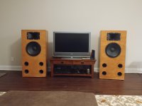
I have recently built a pair of speakers using eminence kappa 15a, eminence N-314T-8 1.4", with eminence PXB2:800 2-Way Speaker Crossover Board 800 Hz and L-pad for horn attenuation. I am using a dragonfly red for the source running into an Onkyo HT-R510 reciever. I am looking to upgrade to a higher quality 2 channel amp and the amp camp amp looks to be a good match. Will the amp camp amp play nicely with the 800 Hz passive crossover? I also noticed the damping factor to be 10 for the amp camp amp but most other amps I have looked at have a damping factor of above 200. I'm not sure exactly what damping factor is and what would be good for this setup. I assume the 8 watts per channel is enough for good listening volume since the woofer is less sensitive than the horn but still around 100db. Any advice would be greatly appreciated.
Thanks,
Will
Thanks,
Will
Attachments
Check your on-off switch, the ACA kit uses a Plastic switch which is sensitive to heat from a soldering iron. Very common switch used in many kits, works well as long as not overheated during soldering.
The channel that works, except the LED stays on, is a symptom.
I'm using the rear switch option that uses the DPDT toggle switch, I don't think I fried it with the soldering iron. However, since setting the bias and letting the amp warm up, that channel seems to turn off now. The LED goes out and I don't measure any voltage through Q1 with the switch off.
Now my only issue is no sound from the other channel. It has voltage through Q1, so I've set the bias, but still no sound. I've checked all the resistors, no cold solder joints as far as I can tell. The only issue is the solder bridge between R2 and R4. Hopefully its visible in my picture.

6L6 wrote the ACA build guide and has a section on troubleshooting, there are voltage measurements for the circuit along with resistance measurements. You can find it in the diy store, ACA kit. Print them and record your values next to his, take a pic of all your measurements and post it. It will take you 10 minutes max, tell all symptoms, LED on? etc. not just what doesn't work, also what does work.
I've checked all the resistors, no cold solder joints as far as I can tell. The only issue is the solder bridge between R2 and R4. Hopefully its visible in my picture.
Not being critical however all of the solder points look cold other than maybe Q2.
I would fire up your iron and reflow everything. Heat the pads well before adding solder to the pad and component leads.
It is desirable to have the solder flow through the board from one side to the other leaving a blob free shiny filled hole on both sides.
- Home
- Amplifiers
- Pass Labs
- Amp Camp Amp - ACA