Just finished the kit (after received it and kept in box for several months,  ). Thanks to the kit and build guide, there is not much to say about the building. The most terrifying thing was actually to find the lost parts.
Hooked it up and gave it a listen, it does bring up the smile to my face after I was disappointed by my DCB1 built last time. Still connect my Audio-GD Ref-7 DAC directly to ACA, just like its ancestor Aleph3 behind the scene, The sound is definitely warmer than Aleph 3 but is still very good. After a few minutes of running, the case is actually warm up quite a bit, which shows a family trait as Aleph 3. Very happy to build this one. 
). Thanks to the kit and build guide, there is not much to say about the building. The most terrifying thing was actually to find the lost parts.Hooked it up and gave it a listen, it does bring up the smile to my face after I was disappointed by my DCB1 built last time. Still connect my Audio-GD Ref-7 DAC directly to ACA, just like its ancestor Aleph3 behind the scene
, The sound is definitely warmer than Aleph 3 but is still very good. After a few minutes of running, the case is actually warm up quite a bit, which shows a family trait as Aleph 3. Very happy to build this one. Attachments
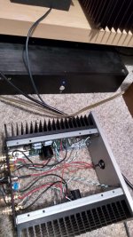
ACA completed!!
Finished the amp today, turned it on, glowing blue LEDs! Let it warm up and adjusted it to 12 volts. Hooked up my Objective O2 and iphone and viola! beautiful music!! Thank you 6L6 for your excellent build guide and all who answered my questions so quickly! Im really blown away by how great this little amp sounds. Looking forward to the tube preamp thats coming soon!!
Finished the amp today, turned it on, glowing blue LEDs! Let it warm up and adjusted it to 12 volts. Hooked up my Objective O2 and iphone and viola! beautiful music!! Thank you 6L6 for your excellent build guide and all who answered my questions so quickly! Im really blown away by how great this little amp sounds. Looking forward to the tube preamp thats coming soon!!
Can C3 come before the input or does it need to be inside the feedback loop?
being inside the loop will reduce its influence on the sound,
its function is to block DC but there would still be no DC within the loop so it should be ok, right?
but there is 3 or 4 volts on the gate of Q4...
oh right, I see now im ignoring R10 and that aspect of the circuit. thanksbut there is 3 or 4 volts on the gate of Q4...
hey everybody, been wondering if anyone else has found errors between the layout (PCB) and the schematic. I've been noticing in the original (V1) schematic and layout that it has the + of C1 (the big output cap) connected directly to the far terminal of one P1. But according to the schematic C1 doesn't connect to the the pot. Also,in the newer versions of the layout (PCB 1.1,1.5,1.6) the + of C1 doesn't seem to be connected to anything. I would really appreciate any help, i have yet to find a version of this schematic that actually perfectly matched its corresponding PCB layout.
THANK YOU!
THANK YOU!
Regarding the C1+ not connected to anything, I think you are forgetting that the PCB is two sided. The built guide has one single picture of the back of a PCB, but there is a version missmatch (it is an older picture).
On V1.6, as you can see in this picture:
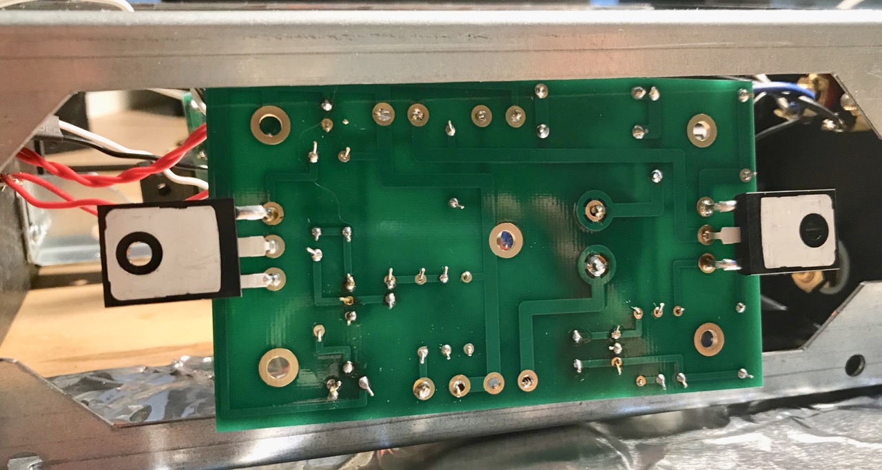
C+, on the other side, is connected.
On my V1.1, I do agree that C+ is actually connected to the Pot. I'd look further into that, as I don't think I have pictures of both sides right now at hand.
On V1.6, as you can see in this picture:
C+, on the other side, is connected.
On my V1.1, I do agree that C+ is actually connected to the Pot. I'd look further into that, as I don't think I have pictures of both sides right now at hand.
Thanks man i realized about C1 and the double layer about 5 mins after I posted. My issue now is with V1. The far end of the pot (that's shown as tied to C1+) should connect to the bottom of R3/R4/C2(-) and the emitter of Q3. The layout has it instead connected to the + of C1 and R1/2/3/4 etc. What's bothering me is that tons of people built that board and apparently it worked, even though it is totally wrong.
Last edited by a moderator:
 I can not make your photo links work. Please try some other form of link to your photos, or better - attach them here.
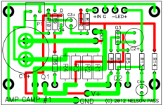
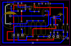
Ok, so I have spent a good hour looking at the schematic and the boards of V1.1, and there is CERTAINLY something that doesn't match the design.
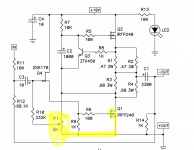
I believe that something like this is what actually got created in the PCB:
There is, without a doubt, a direct connection between P1 and C1+.
What effects can this have in the AMP, the audio, the expected lifespan?
Perhaps other important side effect is that the R15 mod from 1.0 to 1.1 appears to be 'floating' there without any influence to the circuit whatsoever. There may be other inconsistencies.
Thanks for taking a look into this. Best regards,
Rafa.
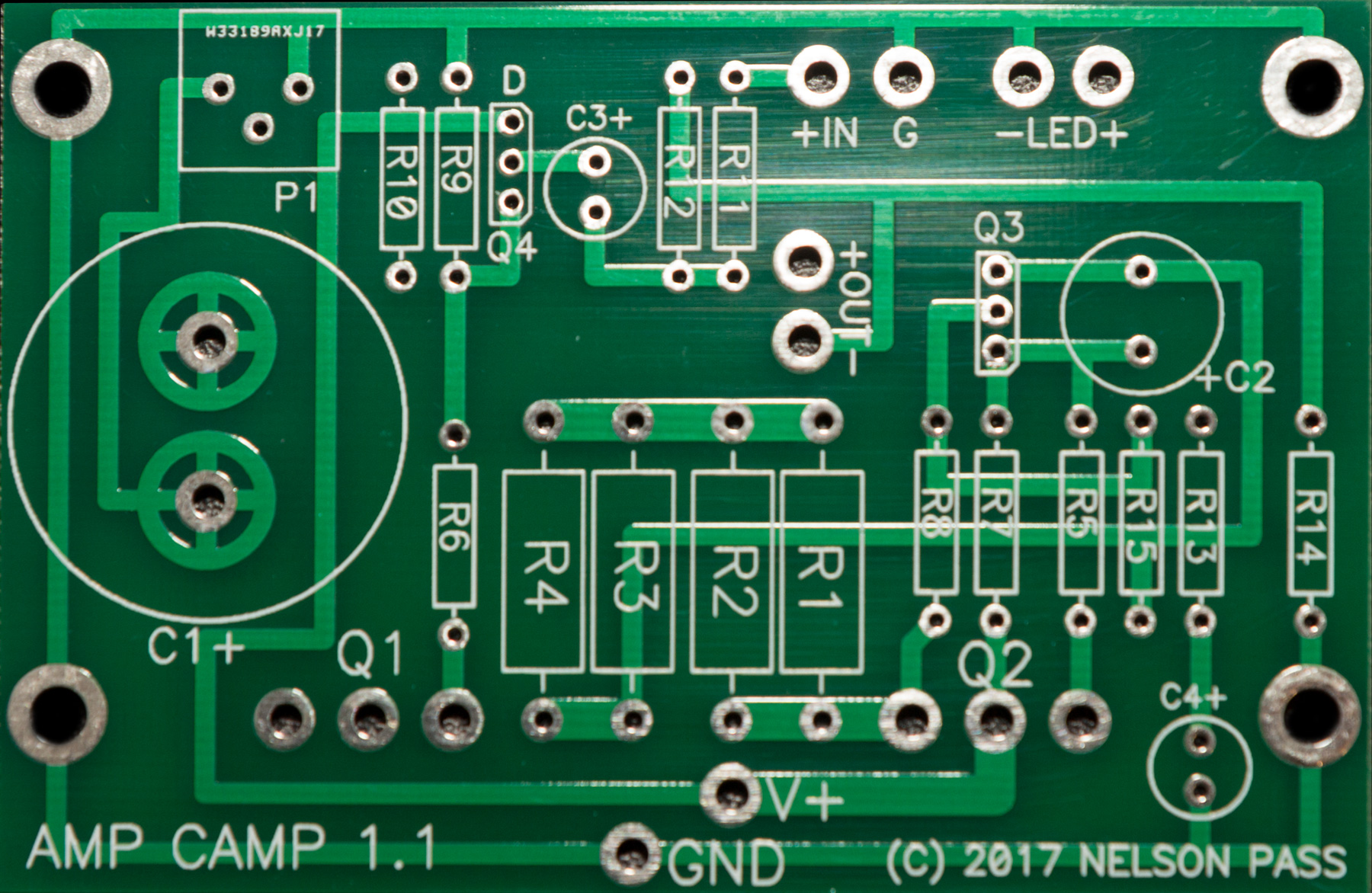
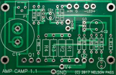
ps: Here is the front side of the V1.1 PCB, I don't have a good picture of the back, perhaps someone has still the gerber files so we can see them 'flat' for better understanding?
I believe that something like this is what actually got created in the PCB:
There is, without a doubt, a direct connection between P1 and C1+.
What effects can this have in the AMP, the audio, the expected lifespan?
Perhaps other important side effect is that the R15 mod from 1.0 to 1.1 appears to be 'floating' there without any influence to the circuit whatsoever. There may be other inconsistencies.
Thanks for taking a look into this. Best regards,
Rafa.
ps: Here is the front side of the V1.1 PCB, I don't have a good picture of the back, perhaps someone has still the gerber files so we can see them 'flat' for better understanding?
Attachments
Last edited:
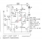
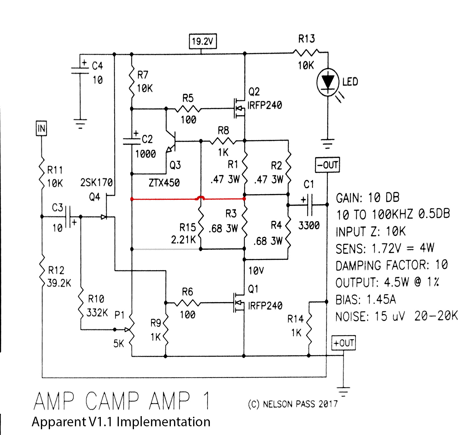
There's a big red line in the middle, and a grayed out connection between R15 and P1 in the first version. And a big diagonal red line from R15 to the middle of R1 and R2 and a grayed out line between R15 and R3 in the second one.Rafa, your schematic looks like the original one to me... I’ve been looking at it for a while and wasn’t able to tell the difference. Can you please highlight your changes?
According to the PCB board ,it is the right schedul.You still don't have it right. The emitter of Q3 goes to the Drain of Q1. Disconnect the top of P1 from everything, then connect it to positive side of C1 and the common point of R1-R4.


- Home
- Amplifiers
- Pass Labs
- Amp Camp Amp - ACA