8 ohm spekers? Maybe try 39k instead of 23k....But when two ACAs are linked together (see attached redrawn diagram) the sound is muddy. ...
Any and all wild-*** guesses appreciated.
Two guesses (questions) then.
1: How have you configured the Grounds? Do they share the chassis ground? Did you use a metal stand off to mount the ACA boards, or plastic?
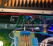
2: Where have you soldered the red wire to? Hope it is to the 'G' pad, but looks like the top of R14? And where is the other end going to - Ground?
Alan
Attachments
Last edited:
Folks:
I wired the Input G vias in each ACA pair together; no improvement.
Alan4411:
The only things connected to chassis ground are the chassis itself and the screens for each of the two torroids. The power GND connections for each pair of the ACA boards go to a dedicated power supply (there are two bridge rectifiers and capacitor boards, one set for each channel). A single metal stand-off was used on each board. I checked the resistance between the standoff and ground on the power supply and measured 0.2R.
Three twisted wires run from the attenuator to the first ACA board in each bridged pair. One wire is for the signal. The other two wires are connected at the attenuator's ground but only one is connected to the Input G via; the other just dangles. I understood that this configuration might reduce noise on the signal line.
Regards,
Scott
If each board is OK in isolation, then that really only leaves ground interaction as a likely cause of issues... and there looks to be a lot of 'wiring' in that enclosure.
Work on one channel at a time and perhaps try altering the power supply wiring such that the second amp power connections (the ground anyway) return to the power supply ground of the first amp, and then have a single ground lead back to the PSU.
The 23k resistor...
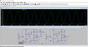
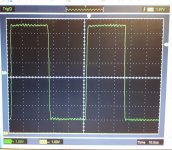
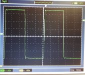
Its important to understand that because of the relatively high output impedance of the ACA, and thus the way the output level is affected by the load impedance, that it is impossible to derive a 'perfect' resistor value that will drive the second amp as a mirror image of the first.
A simulated bridge ACA design shows that around 34k is optimal for a pure 8 ohm loading, but the reality is that the real build will differ slightly in output impedance to sim... but I would have thought it close enough.
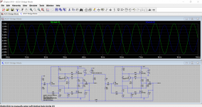
First image shows 8 ohm loading, the second 4 ohm.
Work on one channel at a time and perhaps try altering the power supply wiring such that the second amp power connections (the ground anyway) return to the power supply ground of the first amp, and then have a single ground lead back to the PSU.
The 23k resistor...
Its important to understand that because of the relatively high output impedance of the ACA, and thus the way the output level is affected by the load impedance, that it is impossible to derive a 'perfect' resistor value that will drive the second amp as a mirror image of the first.
A simulated bridge ACA design shows that around 34k is optimal for a pure 8 ohm loading, but the reality is that the real build will differ slightly in output impedance to sim... but I would have thought it close enough.
First image shows 8 ohm loading, the second 4 ohm.
Attachments
Mooly:
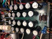
Each channel of two ACA boards ties into its own power supply capacitor board; on the bottom right are two sets of power supply outputs, one for each ACA board. The top right is power entry (from a bridge rectifier). I understand your point, but suspect that wiring the power supply ground for the second ACA board to the ground on the first will not be an improvement over the existing arrangement.
Unless I hear something to the contrary, I'll try your idea out tomorrow.
Regards,
Scott
Attachments
Scott,
Scratching my head on this...
First can you confirm that the BOZ Left and Right output ''Grounds'' connect to the bundle of grounds at the pot (attenuator) and then to the ACA board Ground pads? I guess the white slips are an identifier, but is there an error somewhere? Best use a multi-meter to check.
Second, off the wall idea, is temporarily wire the pot out completely (link the output from the BOZ straight to the inputs of the ACAs). Now turn the 25k trimmer pots on the BOZ all the way down. Switch on and feed in a signal, slowly turn the 25k pots up and see if that sounds better?
What value is your 'attenuator' by the way and any reason to put it in between the BOZ and ACA ?
One more thought, you are trying a quality input rather than just a phone or iPad?
Alan
Mooly:
Each channel of two ACA boards ties into its own power supply capacitor board; on the bottom right are two sets of power supply outputs, one for each ACA board...………………………………..
Its difficult to fully see how it all interacts from pictures but I think in essence you have to count each amplifier pair in a given channel as essentially a single unit as far as grounding goes. Try what I suggested and see where that gets you.
I bought the LRS-150-24 (see post 6900 in this thread)
, I would have to check to be sure and I've not fired the amp up yet to see/hear if it's OK. But I don't anticipate any issues from the spec. If you are concerned you could implement a CRC.... Type filter on the output and tweek up the voltage on the psu to compensate.
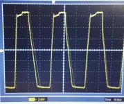
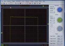
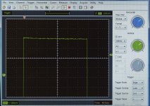
The LRS supplies have quite a bit more HF noise than the GST ones and this can be seen as more noise on the tops & bottoms of square waves.
Please see photos
GST noise is about 120mV with a clean waveform
LRS noise is about 140mV with a rough waveform
Attachments
Last edited:
I tried a CLRC filter with the inductance in the Pos lead but this did not change the squarewave noise - I suspect the noise was creeping in on the earth leg.
However, a CLRC with inductors in both legs does reduce HF noise but then you loose the low output impedance of the SMPS o/p. Also CLRC filters have to be very carefully designed to avoid LF resonances.
I have noticed that the ACA is sensitive to PSU characteristics so I suspect that the GST supplies will sound better.
I did not try a listening test because the LRS supply I bought was 36V ( adjustable from 30 - 39V ) I intend to feed the LRS into a linear voltage regulator which will output about 24V and will have noise levels in the 100uV region.
Will report how it sounds once it's done
mike
Last edited:
Folks:
I've been playing with a number of your suggestions to no apparent effect, but have discovered something interesting. There are two environments in which I've tested this integrated amplifier: (1) on my workbench, where I use an iPhone as the input source and Radio Shack Minimus 7 speakers, and (2) in my main stereo, where the source is a music server feeding my Aleph P 1.7 preamplifier feeding the ACA integrated amplifier connected to Egglestonworks Andra loudspeakers. Up until this morning, I had turned the attenuator on my Aleph P 1.7 all the way up (i.e., -0 dB). In both set-ups, the distortion has been both the same and readily apparent.
I normally listen to my main stereo at about -30 dB. This morning, I hooked up the ACA amplifier to my main stereo, turned the Aleph P preamp attenuator all the way up and got the distortion again. But then I turned the attenuator on the Aleph P down to about -35 dB and turned up the attenuator on the ACA preamp to get the same relative volume and the distortion disappeared. The attenuator on the ACA integrated amp was turned all the way up and the music sounded great -- no distortion. I then raised the Aleph P's attenuator to -15 dB and lowered the attenuator on the ACA integrated amp and heard the distortion creeping in again, albeit less noticeable than when the Aleph P's attenuator was set at -0 dB.
Is the gain on the BOZ preamp in my ACA integrated amp too high? Is there another likely causation for the effect I've noticed?
Regards,
Scott
Bridged Mono vs. Parallel Mono
I recently completed my two ACAs and wired them for bridged mono and I’m very happy with the resulting sound. I have several different speakers, all of which are 8 ohm and below impedance and I also have some magneplaners which are obviously low impedance and a difficult load. I don’t expect these amps to drive the Magneplaners but would be curious to hear them properly configured for low impedance. I noted from the amp spec sheet that wired for bridged mono they’re more appropriate for impedances of 8 to 16 ohm, which I’ll never reach. However, the parallel mono impedance spec of 4 to 8 ohms would appear to be more appropriate for 8 ohm and below speakers. I also understand a larger damping factor is preferred, although ultimately it probably doesn’t make much difference. Could someone describe what differences I might expect if i rewire the amps for parallel mono instead of bridged mono? Thanks very much for any insight.
I recently completed my two ACAs and wired them for bridged mono and I’m very happy with the resulting sound. I have several different speakers, all of which are 8 ohm and below impedance and I also have some magneplaners which are obviously low impedance and a difficult load. I don’t expect these amps to drive the Magneplaners but would be curious to hear them properly configured for low impedance. I noted from the amp spec sheet that wired for bridged mono they’re more appropriate for impedances of 8 to 16 ohm, which I’ll never reach. However, the parallel mono impedance spec of 4 to 8 ohms would appear to be more appropriate for 8 ohm and below speakers. I also understand a larger damping factor is preferred, although ultimately it probably doesn’t make much difference. Could someone describe what differences I might expect if i rewire the amps for parallel mono instead of bridged mono? Thanks very much for any insight.
The LRS supplies have quite a bit more HF noise than the GST ones and this can be seen as more noise on the tops & bottoms of square waves.
Please see photos
GST noise is about 120mV with a clean waveform
LRS noise is about 140mV with a rough waveform
I tried a CLRC filter with the inductance in the Pos lead but this did not change the squarewave noise - I suspect the noise was creeping in on the earth leg.
However, a CLRC with inductors in both legs does reduce HF noise but then you loose the low output impedance of the SMPS o/p. Also CLRC filters have to be very carefully designed to avoid LF resonances.
I have noticed that the ACA is sensitive to PSU characteristics so I suspect that the GST supplies will sound better.
I did not try a listening test because the LRS supply I bought was 36V ( adjustable from 30 - 39V ) I intend to feed the LRS into a linear voltage regulator which will output about 24V and will have noise levels in the 100uV region.
Will report how it sounds once it's done
mike
Hmmm 'thanks' for this info, I'm mildly concerned now. I had looked at the bulk ripple and not been bothered. Looking at the content of it, I'm now a little more worried. Something like Jumas simple capacitance multiplier circuit might be in order... I still have a little room in the chassis!
Hmmm 'thanks' for this info, I'm mildly concerned now. I had looked at the bulk ripple and not been bothered. Looking at the content of it, I'm now a little more worried. Something like Jumas simple capacitance multiplier circuit might be in order... I still have a little room in the chassis!
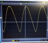
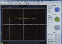
Today I did some better defined measurements.
I have attached the results
I would be very interested to see the results from a cap multiplier but personally I would expect better results if you put C L ( in both legs ) C upstream but no harm in trying the multiplier - the CLC could be plan B
")
Best to design the CLC in spice because you will need some R included to damp any resonances & 1st cap should be smaller than second one. Let me know if you need any help
mike
Attachments
What’s there to not understand?
Zen Mod, thanks for providing a synopsis of the advantages of different modes of operation. It’s useful knowledge that I’ll put to use. However, as could be discerned from my initial post, I was really looking for more subjective info on what changes in sound I might expect or advantages or disadvantages by rewiring. Some people don’t have much knowledge on how electronic circuits work. Your post seems to presume this to be basic knowledge that everyone should know. Just isn’t so. Anyway, thank you.
horses for courses
bridged - augmented in voltage domain
paralleled - augmented in current domain
higher ohmic value load demands more voltage
lower ohmic value load demands more current
what's there to not understand ?
Zen Mod, thanks for providing a synopsis of the advantages of different modes of operation. It’s useful knowledge that I’ll put to use. However, as could be discerned from my initial post, I was really looking for more subjective info on what changes in sound I might expect or advantages or disadvantages by rewiring. Some people don’t have much knowledge on how electronic circuits work. Your post seems to presume this to be basic knowledge that everyone should know. Just isn’t so. Anyway, thank you.
simple - if you hear that single ACA is starting to sound breathless , or choking  , what else to do than adding another ACA to help
for higher ohmic value loads (8R and more) , add another ACA with bridging , so you are getting more cojones in voltage domain , what is needed
for lower ohmic value loads (4R and beware! of less) , add another ACA with paralleling , so you are getting more cojones in current domain , what is needed
so , main difference - if you hear lack of power , when you double them in either way , you'll not hear lack of power up to higher SPL
, what else to do than adding another ACA to helpfor higher ohmic value loads (8R and more) , add another ACA with bridging , so you are getting more cojones in voltage domain , what is needed
for lower ohmic value loads (4R and beware! of less) , add another ACA with paralleling , so you are getting more cojones in current domain , what is needed
so , main difference - if you hear lack of power , when you double them in either way , you'll not hear lack of power up to higher SPL
- Home
- Amplifiers
- Pass Labs
- Amp Camp Amp - ACA