This discussion of a high current, low voltage ACA using high current FETs will result in a circuit that may indeed sound wonderful, but will not be an ACA.
By that logic the ACA isn't the ACA and should instead be called the Zen 5 (or thereabouts...) Nomenclature doesn't matter.
By all means do whatever you like with your pile of parts and chassis sold under the name of ACA!
It should be remembered that one of the aims of Mr. Pass is to foster experimentation
Precisely!!

Vince, are you not interested in the details on the ACA that Tony mentioned to build your very own ACA V3.00B?
Never heard of the version you mention.
I have a couple pair of Sonus Faber speakers from 2000 era. Grand Piano and Concertos. 86db effecient. They sound great with the 19v, linear supply ACA and B1, BA3-pre and boz-j. I hear special things. ACA is not like other amps I tried. The sound is different.
I know talking about sound is avoided here. Bit odd considering what we do. Kind of like making wine but keeping your tasting results to yourself.
I guess it's complicated and personal. So I appreciate your input. I'll pass on the 300B. No pun intended.
You got it, the magic of small amps is powerful. They say the smaller the more amazing.... ACA is not like other amps I tried. The sound is different....
Changing to a different MOSFET with a MUCH larger max-current specification, won't change the amount of Class-A bias current flowing in your ACA. Bias current is regulated to a fixed and constant value by R1-R4 and Q3 in the ACA schematic of post #1. Since none of those components are changed or even touched when swapping output transistors, bias current does not change.
You will however need to adjust potentiometer P1 after changing the output transistors. This re-centers the output swing and ensures symmetrical clipping, i.e., it maximizes the available undistorted output power before clipping.
You will however need to adjust potentiometer P1 after changing the output transistors. This re-centers the output swing and ensures symmetrical clipping, i.e., it maximizes the available undistorted output power before clipping.
An interesting and somewhat philosophical discussion...
At what point is a modified/tweaked ACA no longer an ACA?
When I built my first pair of boards, I already had some ideas about where I wanted to take this little amp. I was already familiar with the Zen V4, and consider the ACA to be a little sister to that amp. My initial modifications were simply component substitutions. I didn't alter the operation of the circuit until I had spent some time listening to a single stereo amp.
The next modification was to address the low input impedance and relatively low gain. Still an ACA, I think, because similar modifications already existed between ACA #1 and version 1.6, which is now being sold through the store.
After that, I slightly altered the R3 & R4 values, thereby increasing the bias current. Still an ACA? I think probably so, but others may differ in opinion.
In terms of changes to sound quality, altering the input impedance feedback definitely made an improvement. Likewise, so did increasing the bias current. But the biggest improvement was bridging a pair of ACAmps, first as RCA-input, self-inverting bridged amps, then as parallel mono blocks. The improvement from bridging the amps made them sound like different designs, though I think most would agree that bridging an ACA still gives an ACA. But what if I include an enclosed SMPS inside the chassis?
I'm currently working on further alterations, including changing the MOSFETS. One of my goals would be to replicate the sound of my parallel bridged amps in a single chassis. At this point, I would agree that this will no longer be an ACA, but a Turbo or even BabelFish (in deference to Mighty ZM) ACA.
Question: If I add a Zen V4 style interactive cap-multiplier to the power rail, does this become a modified V4 or remain a modified ACA?
Hey MOSFET idea from a NOBE, 80 V rails
After two years of reading and subscribing to a few threads on DIY audio building a few headphone amplifier‘s and now my first Amp Camp Amp and probably a couple thousand hours of videos on stereo amplifier repairs both home and car audio. The amp camp amp seems like the perfect platform for somebody with very little knowledge but likes to tinker in modify as a learning tool. Couple days ago I was watching one of my favorite YouTube car stereo amplifier rebuilder. He was working on a very high-end 10,000 W car stereo amplifier using MOSFETs that had 80 V rails. The cars 12 V would go in to the amplifier go through I switch mode power supply that would raise the voltage to 80 V at that point the Amp Camp Amp popped to mine and a lightbulb went on. My thoughts can I take these MOSFETs put them in the amp camp amp board and play with the resistors in transistors until it worked would it still be an Amp Camp Amp?. Am I totally wrong here to attempt such a project. Is this one of those cases where (“you do not even know what you do not even know so therefore you’re dangerous”)?.
An interesting and somewhat philosophical discussion...
At what point is a modified/tweaked ACA no longer an ACA?
When I built my first pair of boards, I already had some ideas about where I wanted to take this little amp. I was already familiar with the Zen V4, and consider the ACA to be a little sister to that amp. My initial modifications were simply component substitutions. I didn't alter the operation of the circuit until I had spent some time listening to a single stereo amp.
The next modification was to address the low input impedance and relatively low gain. Still an ACA, I think, because similar modifications already existed between ACA #1 and version 1.6, which is now being sold through the store.
After that, I slightly altered the R3 & R4 values, thereby increasing the bias current. Still an ACA? I think probably so, but others may differ in opinion.
In terms of changes to sound quality, altering the input impedance feedback definitely made an improvement. Likewise, so did increasing the bias current. But the biggest improvement was bridging a pair of ACAmps, first as RCA-input, self-inverting bridged amps, then as parallel mono blocks. The improvement from bridging the amps made them sound like different designs, though I think most would agree that bridging an ACA still gives an ACA. But what if I include an enclosed SMPS inside the chassis?
I'm currently working on further alterations, including changing the MOSFETS. One of my goals would be to replicate the sound of my parallel bridged amps in a single chassis. At this point, I would agree that this will no longer be an ACA, but a Turbo or even BabelFish (in deference to Mighty ZM) ACA.
Question: If I add a Zen V4 style interactive cap-multiplier to the power rail, does this become a modified V4 or remain a modified ACA?
After two years of reading and subscribing to a few threads on DIY audio building a few headphone amplifier‘s and now my first Amp Camp Amp and probably a couple thousand hours of videos on stereo amplifier repairs both home and car audio. The amp camp amp seems like the perfect platform for somebody with very little knowledge but likes to tinker in modify as a learning tool. Couple days ago I was watching one of my favorite YouTube car stereo amplifier rebuilder. He was working on a very high-end 10,000 W car stereo amplifier using MOSFETs that had 80 V rails. The cars 12 V would go in to the amplifier go through I switch mode power supply that would raise the voltage to 80 V at that point the Amp Camp Amp popped to mine and a lightbulb went on. My thoughts can I take these MOSFETs put them in the amp camp amp board and play with the resistors in transistors until it worked would it still be an Amp Camp Amp?. Am I totally wrong here to attempt such a project. Is this one of those cases where (“you do not even know what you do not even know so therefore you’re dangerous”)?.
An extension to indra's question:
Would the ACA benefit from using a low voltage, high current fet, like IRFP044, or IRFZ40 and so on?
I remember Mr. Pass recomending such devices for some variants of the Zen amp, mostly because of their high Gm and lower distortion.
I think Mr Pass chose the mosfets carefully. If you test the irfp044 or indeed the irfp054 I think you will find that they are less linear at the normal operating currents that lower current models. Also because they have higher transconductance the OLG will be higher so feedback will be more - not sure if this will be a benefit or not.
I have had a good results using IPP600N25N3 they also have higher transconductance but I increased the CLG to 10 & thus kept the amount of FB more or less the same. They show reasonable linearity around 2 amps. Trouble is they are TO220s so you will either need a new board or extension leads !
mike
My thoughts can I take these MOSFETs put them in the amp camp amp board and play with the resistors in transistors until it worked would it still be an Amp Camp Amp?.
Yes, you can and yes it would be.
Am I totally wrong here to attempt such a project. Is this one of those cases where (“you do not even know what you do not even know so therefore you’re dangerous”)?.
Not at all!! In fact you'll be learning and experimenting and having a grand time. As long as you are fine with the possibility of letting the smoke out, (which would of course admit you to the Fearless Amplifier Builder's Club) then by all means proceed and have fun!
Let us know what you figure out. I'm looking forward to hearing about your results. And please take lots of photos and post them.
80 V rails MOSFET used in 10,000 W car audio amplifier
Here is the link to the YouTube video by barevids YouTube
I have to go back to a few videos and listen when he actually name is the part number for the specific MOSFETs that were used. Forget the name of the manufacture of amplifier that he was working on go to their website and download the schematics a repair manual to research the MOSFETs I would be using. This particular YouTuber Preformance live stream repairs that are sometimes several hours long from beginning to end goes through all the diagnostics and replacement of parts so the view can experience every procedure preformed.
For those newbies reading this form here’s some additional YouTube personnel who put out videos of Repair on amplifiers and radio components I’ll put a list of their names below I’ve been watching them for the last two or three years to educate myself .
Blueglow Electronics YouTube channel
12Voltvids YouTube channel
Mr Carlson’s Lab YouTube channel
ElPaso TubeAmps YouTube channel
Uncle Doug YouTube channel
The above listed YouTube channels specialize either in tube amplifiers or the general repair of all amplifiers stereo equipment cassette deck etc. including constructing from scratch tube amplifiers from Ground Zero through completion. There’s also some good videos about point to point construction for us newbies who are thinking about attempting to go down that road and teach ourselves through the experience of others who are superior at their craft .
My progress will be slow but when I get there I will post pictures and components used down my path of learning more of modifying the amp amp amp. I own and run to full-time businesses and also attend college night classes so taking this on as a hobby on the side will take quite a long time.
sometimes is best to be precise ......
which mosfets, exactly?
Here is the link to the YouTube video by barevids YouTube
I have to go back to a few videos and listen when he actually name is the part number for the specific MOSFETs that were used. Forget the name of the manufacture of amplifier that he was working on go to their website and download the schematics a repair manual to research the MOSFETs I would be using. This particular YouTuber Preformance live stream repairs that are sometimes several hours long from beginning to end goes through all the diagnostics and replacement of parts so the view can experience every procedure preformed.
For those newbies reading this form here’s some additional YouTube personnel who put out videos of Repair on amplifiers and radio components I’ll put a list of their names below I’ve been watching them for the last two or three years to educate myself .
Blueglow Electronics YouTube channel
12Voltvids YouTube channel
Mr Carlson’s Lab YouTube channel
ElPaso TubeAmps YouTube channel
Uncle Doug YouTube channel
The above listed YouTube channels specialize either in tube amplifiers or the general repair of all amplifiers stereo equipment cassette deck etc. including constructing from scratch tube amplifiers from Ground Zero through completion. There’s also some good videos about point to point construction for us newbies who are thinking about attempting to go down that road and teach ourselves through the experience of others who are superior at their craft .
My progress will be slow but when I get there I will post pictures and components used down my path of learning more of modifying the amp amp amp. I own and run to full-time businesses and also attend college night classes so taking this on as a hobby on the side will take quite a long time.
I am entirely in favor of experimentation with the ACA. As it is being discussed there are all kinds of components that can be altered or exchanged. However, I would like to insist that experimentation be done using a new set of PCBs so that you can compare the result you obtain from your experimentation directly using an ACA vs modified ACA with all other component of the system kept the same. This would not only be interesting but also very valuable information for this board to have.
^This
Absolutely, it’s way more instructive to have different board sets for experimenting. Now that I have my parallel monoblocks in place, they will be the benchmark to compare other design mods against.
I will have a set of six new boards to play with after Xmas. Different layout with some new features. Details will be forthcoming...
And yes, I have a pair of Aleph J boards that are waiting for a good home. Was hoping that a Dissipante 4U/400 chassis with UMS heat sinks would materialize. But I have a drill press and proper drill and tap sets, so I may be doing more metal work in the coming new year.
It’s all good
Last October 27, we did a diy build-out with 17 participants, there were 34 boards of our own local design based on the NP circuit....
we started at around 8 am and by 3 pm we had one fully built amp making music...and all who participated had their amps calibrated to 1/2 b+ rail...
what we have learned:
1. that amp will work the first time when the right parts are inserted correctly
2. to setup the boards to 1/2 the B+ rails. the 330k trimpot is adjusted, this is done when the amp has warmed up. this is about the only adjustment required...
3. sound is comparable to a 300b in a blind test...very nice...
in the first quarter of 2019 we are again holding another diy build out this time with a target participation of 50 local diy'ers....
the diy build-out was indeed a lot of fun......
I think Mr Pass chose the mosfets carefully. If you test the irfp044 or indeed the irfp054 I think you will find that they are less linear at the normal operating currents that lower current models. Also because they have higher transconductance the OLG will be higher so feedback will be more - not sure if this will be a benefit or not.
I have had a good results using IPP600N25N3 they also have higher transconductance but I increased the CLG to 10 & thus kept the amount of FB more or less the same. They show reasonable linearity around 2 amps. Trouble is they are TO220s so you will either need a new board or extension leads !
mike
My experiments with a Zenlite head amp (Head Lamp) led me to believe that the mosfet has a huge role in the sound of the amp, in that particular topology.
I started with IRFZ44 @ 0.3A but due to high capacitance the top end was distorted.
Went in succession to IRF610, 640, Z34, adjusting the current upwards a bit and found the amp was lacking control, the mids were no longer lush, transparent, the amp had no soul.
Frustrated changed back to IRFZ44 @0.7A and everything slotted in place - precision, character, slam, top end.
This amp doubled also as my main amp for quite some time, running 95dB speakers.
Then I built the ACA with IRFP240.
Sounds great, but a bit cold and more analytical compared to the Head Lamp.
Now am running a MoFo with IRFP150 which I like very much.
I've got a spare set of PCBs for an ACA with the exact same components as the one in use. It should be easy to solder IRFP150 and compare the two ACA amps.
Great discussion BTW.
Hooray!
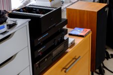
Have finished building the Amp Camp Amp today!
Our original Amp was a Musical Fidelity P150. Lots of info about it and the P3 Preamp. It has been ok for years but recently replaced all the Caps etc and decided we want a better amp, and found the ACA on DiyAudio forum.
The P150 is now off. Next will be replacing the Pre-amp. Have the Lender Preamp circuits arrived and now chasing the components.
The ACA kit arrived about a week ago and built it during the week. Decided to turn the circuit boards so the hot resistors are above the caps, not below them. Everything else is standard. Sounds excellent!
Attachments
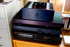
Decided to turn the circuit boards so the hot resistors are above the caps, not below them.
What a great idea! Those big resistors get hot. I'm surprised that it was overlooked in the circuit layout and build guide.
- Home
- Amplifiers
- Pass Labs
- Amp Camp Amp - ACA