Pass DIY Addict
Joined 2000
Paid Member
These little amps are starting to spring up like mushrooms lately ") Nice work, Mutuano!
Nice work, Mutuano!
I'll be building another one with my 11 year old daughter for her birthday. I'm using recycled sinks and a slab of nicely figured Walnut with Tung Oil Finish. A pair of matching speakers with MarkAudio CHR-70 drivers will be paired with it.
Nice work, Mutuano!I'll be building another one with my 11 year old daughter for her birthday. I'm using recycled sinks and a slab of nicely figured Walnut with Tung Oil Finish. A pair of matching speakers with MarkAudio CHR-70 drivers will be paired with it.
Are these amps supposed to say "pwwweeep" when starting up?
Just turned on my first ACA. The second one hasn't been connected to speakers yet, but at least it didn't explode.
Yes. Most folks say it's more of a farting noise
It's the caps charging up. Quite normal.
You should also hear a little pop when you turn them off. That's the cap discharging.
Yes. Most folks say it's more of a farting noise
It's the caps charging up. Quite normal.
Ah, the big ones in the output?
The turn-on sound is normal. And a small turn-off thump.
I think it sounds like a cartoon person slurping up one strand of spaghetti.
Step 48 of the guide has a video showing it.
Amp Camp Amp V1.6 Build Guide - diyAudio Guides
I think it sounds like a cartoon person slurping up one strand of spaghetti.
Step 48 of the guide has a video showing it.
Amp Camp Amp V1.6 Build Guide - diyAudio Guides
Every few days or so when I actually pull myself away from my retail FW M2 (just can't resist that amp!!!), and I swap cables and let the two mono block ACA's do the work (Bridge mono block RCA config)... each time they seem to get better and better and I was quite happy from the start. I'm continually astonished at how great those ACA's are!...
So now for my dumb questions (When answering, lol, please dumb it down a little for me, I only understand enough to be dangerous)
1. Since I'm STILL!! building a pre amp (its only been a year, lol), I have read tons and tons of threads on here, and I notice for other amps people bias the amp they have built, then maybe a few days later they bias it again... is this at all necessary for the ACA, or any benefit to doing so?
2. I see this other way of setting up the amp for mono block RCA configuration... Parallel RCA mono block config... could someone explain what the sonic differences or benefits would be in this configuration?
Thanks in advance, and sorry for my dumb questions
1. "biasing" ACA is not setting Iq (self-setting in this case) , but setting output node voltage potential , to ensure few things , of which symmetrical clipping is most important one ; so , not so critical in time/temp. domain , as Iq is
2.when you need more volts (higher ohms loudspeakers , but sorta inefficient) you go to bridge ; when you need more amps (lower ohms loudspeaker) you go to parallel
2.when you need more volts (higher ohms loudspeakers , but sorta inefficient) you go to bridge ; when you need more amps (lower ohms loudspeaker) you go to parallel
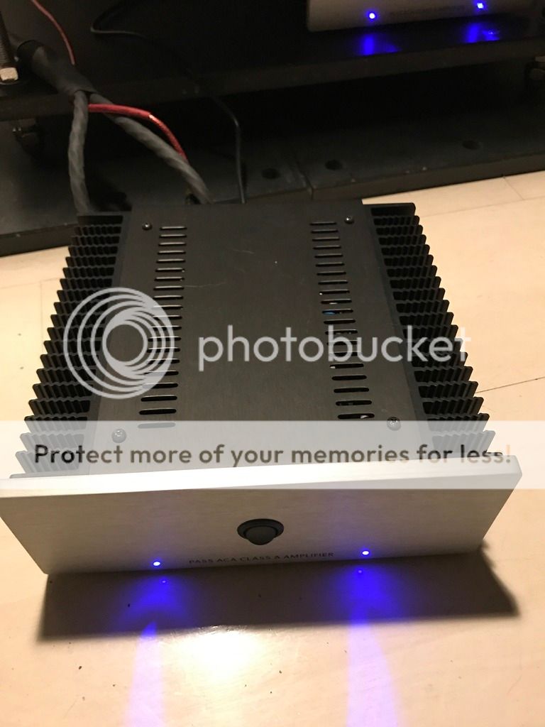
Just finished (almost) mine.
Heat soak biasing at present.
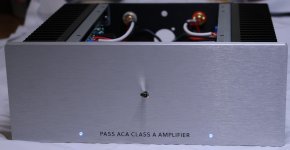
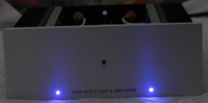
I chose the blue led option, It's in keeping with PL after all
But I detest glarey strong lights, so I played with R13 and ended up with 56k. (24v supply)
Bright enough to be seen in a well lit room, yet in a dark room barely annoying if viewing straight into the leds.
Yes I'll post pics when I can so you can see the led results.
Heat soak biasing at present.
I chose the blue led option, It's in keeping with PL after all
But I detest glarey strong lights, so I played with R13 and ended up with 56k. (24v supply)
Bright enough to be seen in a well lit room, yet in a dark room barely annoying if viewing straight into the leds.
Yes I'll post pics when I can so you can see the led results.
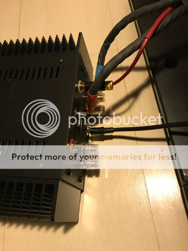
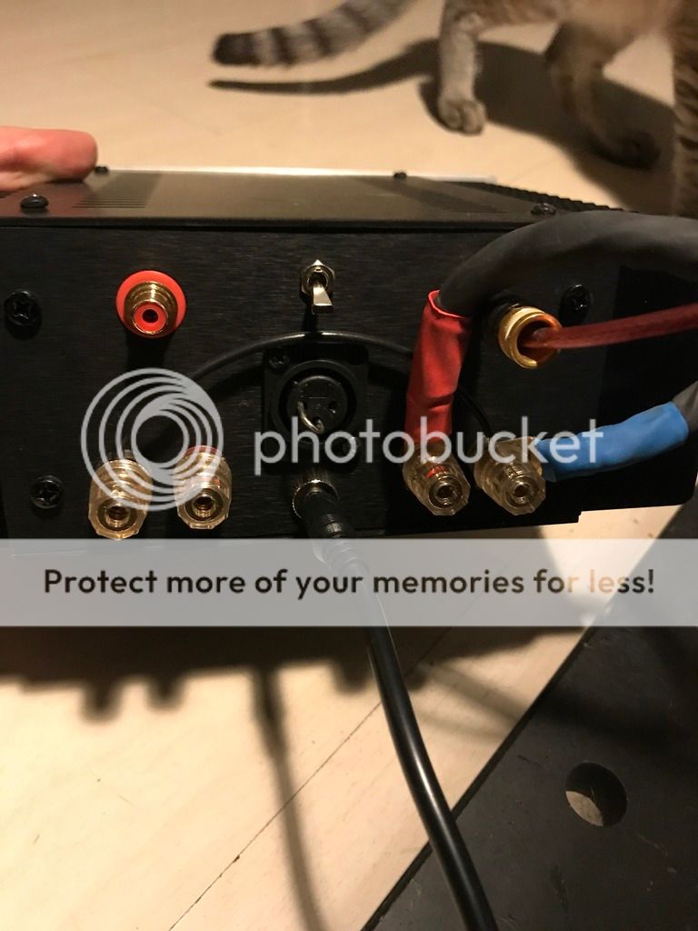
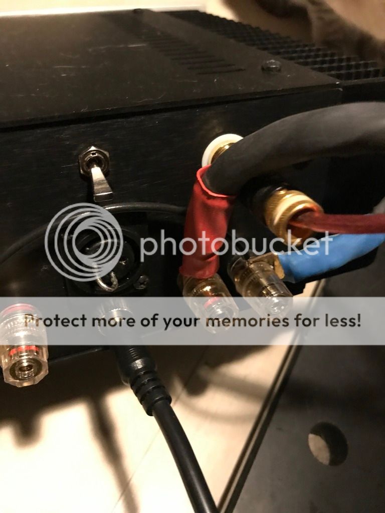
Some pics as promised.
I need to make a blanking plug for the xlr and rear switch holes.
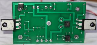
Things I changed;
Vishay 0.01uf caps across C1, C2, C4.
Vishay Dale rn60 resistor for R11 (Because I had it on hand, would've changed some others but didn't have any handy).
Used the supplied 'rear' toggle switch for the main power switch on the front (Homage to my x150.5).
4mm cable for most power wiring and 5mm from power socket to power switch.
Silver plated teflon insulated wire for speaker connection.
Shielded cable for input.
Longer board stand off to space the board off the heatsink a touch more, also needed that extra bit for the Vishays.
Mounted the red posts on the outside (my OCD ) which meant a minor change to the rear panel wiring.
I pre wired the boards so that I could clean the whole lot in one go before mounting them to the heatsinks.
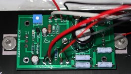
I also biased it to 10v to drop heat output a little.
I'm not concerned about the side effects of doing this.
To give an idea of what its like with the 56k LED resistors.
Pic 3 is a well lit room with power off.
Pic 4 is a well lit room with power on.
Pic 5 is a very dark room with power on.
I need to make a blanking plug for the xlr and rear switch holes.
Things I changed;
Vishay 0.01uf caps across C1, C2, C4.
Vishay Dale rn60 resistor for R11 (Because I had it on hand, would've changed some others but didn't have any handy).
Used the supplied 'rear' toggle switch for the main power switch on the front (Homage to my x150.5).
4mm cable for most power wiring and 5mm from power socket to power switch.
Silver plated teflon insulated wire for speaker connection.
Shielded cable for input.
Longer board stand off to space the board off the heatsink a touch more, also needed that extra bit for the Vishays.
Mounted the red posts on the outside (my OCD
) which meant a minor change to the rear panel wiring.I pre wired the boards so that I could clean the whole lot in one go before mounting them to the heatsinks.
I also biased it to 10v to drop heat output a little.
I'm not concerned about the side effects of doing this.
To give an idea of what its like with the 56k LED resistors.
Pic 3 is a well lit room with power off.
Pic 4 is a well lit room with power on.
Pic 5 is a very dark room with power on.
Attachments
Not having a separate dac I was wondering how to feed the ACA. Bought a second hand Yamaha WXC-50. It works. Connection wise it is great and easy. It streams Tidal over wifi. However it doesn't sound nice. Then I had a bright idea and connected my laptop directly to the ACA. It works and sounds even a little better! Now there is room for improvement!
First I will try this with a dac in between. Got a Chord Mojo coming [emoji41]
First I will try this with a dac in between. Got a Chord Mojo coming [emoji41]
Last edited:
Can we put the SMPS power supply like the meanwell LRS 100-24 directly inside aca cabinet (diy case to be build afterwards) ie amp and smps in same case.
By doing so we can get the mains supply lines to the amp cabinet and connect it to both, 1. the SMPS for ACA and
2. and in parallel to a small transformer which will power the preamp in the same case
3. in parallel to another small 5v transformer which will power the digital side ie ardunio which will provide option for remote control and small lcd screen.
OR can we use the usual external SMPS supply, and use dc-dc converters for preamp and ardunio side with all the ardunio and related parts, + preamp + aca amp + dc-dc converters for each part (preamp , ardunio) , in same cabinet.
Last edited:
......
I also biased it to 10v to drop heat output a little.
.........
clarify, please.
which voltage PSU you're using ?
I also biased it to 10v to drop heat output a little.
I'm not concerned about the side effects of doing this.
One side effect of reducing the midpoint to 10 v (aside from asymmetrical clipping) is actually increased heat dissipation. This is due to the change in voltage across R7 (10k) changing slightly the operating point of bias regulator Q3.
It will only be by a watt or two but its a change in the wrong direction. Increasing the midpoint voltage will reduce the overall dissipation very slightly but its only a couple of percentage points.
Stick to the recommended operating point would be my advice.
clarify, please.
which voltage PSU you're using ?
24vdc
One side effect of reducing the midpoint to 10 v (aside from asymmetrical clipping) is actually increased heat dissipation. This is due to the change in voltage across R7 (10k) changing slightly the operating point of bias regulator Q3.
It will only be by a watt or two but its a change in the wrong direction. Increasing the midpoint voltage will reduce the overall dissipation very slightly but its only a couple of percentage points.
Stick to the recommended operating point would be my advice.
DOH
Ah well, shows what I dont know
Time to open and readjust to 12v.
At least it's such an easy simple thing to do on these
Edit.
So in that case, I should actually be aiming for half power supply, correct ??
My supply loaded with the amp is 23.9v, half would be 11.95v
hhmm nit picking to the extreme ?
Last edited:
Possible idea for minimising/eliminating switch on and switch off noise.
Any experimenters out there who may be interested in minimising the noise the ACA makes at power on and shutdown may find this idea a basis to develop.
A possible approach to adding a silent start/shutdown to the ACA
Any experimenters out there who may be interested in minimising the noise the ACA makes at power on and shutdown may find this idea a basis to develop.
A possible approach to adding a silent start/shutdown to the ACA
- Home
- Amplifiers
- Pass Labs
- Amp Camp Amp - ACA