With that much heatsinking you could maybe do a bridged ACA
Mark
Yes!! I bought a few extra pairs of PCBs just for the occasion.
'Hi, my name is John, and I have a heatsink addiction'
How would.you. bridge them?
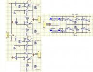
The attached file bridgeACA.pdf shows a diagram of a possible way to bridge two similar amplifiers. I am suggesting that a high quality transformer be used to invert the phase of one input signal for the bottom ACA relative to the upper ACA.
- The transformer is JENSEN JT-123-FLPCH . Its salient properties are found in a link in Post #351 [Zen Mod author] of the Thread entitled F6 Amplifier in the Pass Labs Forum. Mr. Pass has recommended using it for DIY F6 amplifiers.
- The transformer has two primary and two secondary windings. Each winding has an impedance of ~600 Ohms. I connected the 2 primary windings in parallel as shown. Please note the half shaded sine wave squiggle, and the bolded circle or dot. They are used exclusively to track the phase of the signal from input all the way to the speaker leads.
- ACA is a phase inverting amplifier; note the sine squiggles at its input and output. In order to have or maintain the correct absolute phase beween the input [at the primary of transformer] and the loudspeaker, the red lead of the loudspeaker must be connected to the output of the bottom ACA.
- The on-off switch at the output, may be as simple as unplugging the negative lead of the loudspeaker from its output post
- There is a coupling capacitor at the output of each ACA. Keep it; or consider the following suggestion which has the potential risk of damage to the equipment. Discard/do not use the output coupling capacitors. Put a Fast Blow fuse [maybe 1-2 A] in series with the output of each amp which is at ~10 VDC above power supply ground. If one accidentally shorted the output of either amp to the chassis which maybe at power supply ground, this fuse will blow; thus protecting the amp and/or the loudspeaker from a surge of Direct Current to ground or common.
- The audio source must not push any DC through the primary windings. It must be capacitor coupled or its output has absolutely no DC offset. DC flowing in any one winding of this transformer is contraindicated by JENSEN due to magnetization and resultant distortion.
I was thinking something like the one I've attached. The downside is that you'll need another power supply for it, but it's requirements are pretty small. I'm going to use one of these to convert unbalanced to balanced for that 50W watercooled SOZ that i've been trying to build since the day I first logged into this crazy place
Attachments
Last edited:
Regardless of the method used to generate, and use the out-of-phase input signals to the 2 ACAs [note post #451 by MEGA-amp], the DIYer will still face the question of how best to connect the outputs of the ACAs. There are three possibilities. I addressed the first two in my earlier post.
N.B. The attached file kept detaching spontaneously! Possible software problem.
- Each ACA retains its output DC blocking/coupling electrolytic capacitor [3,300 uF].
- Discard/do not use the electrolytic capacitor of each ACA. But the DIYer must protect both amps and the loudspeaker with fast blow in-line fuses; in case of accidental shorting of the amps' output to power supply ground [e.g the grounded chassis].
- The third option is a compromise of both preceeding options. Use one DC blocking/coupling electrolytic capacitor and one fast blow fuse only. The simplified diagram is in the attached bridgeACA1.pdf.
- What do I do with the unused electrolytic capacitor from the second ACA [3,300 uF, paid for!]? Use it in parallel with the other one in its target ACA [ shown dotted]. Double the capaticance can only improve the overall performance of the bridge amp.
- Do not connect the loudspeaker.
- Allow both amps to reach operating temperature.
- No input signal.
- Adjust potentiometer P1 in the upper ACA so as to increase the DC voltage at its output node to +10.25 VDC or higher if you choose to 10.5 VDC. The positive lead(s) of the electrolytic capacitor(s) is connected to this output node.
- Adjust potentiometer P1 in the lower ACA so as to decrease the DC voltage at its output node to + 9.75 VDC or lower if you choose to 9.5 VDC
- Insert the fast blow fuse [1-2 A] and connect the loudspeaker.
- Confirm that the electrolytic capacitor is properly polarized. Meaning it has 1/2 Volt or 1 V [your choice] across it.
- Monitor this voltage on turn-on also from a cold start to ensure that the capacitor is also properly polarized.
- There is absolutely no relationship between the phase of the input signals to the ACAs and the polarity tweaks across the output blocking capacitor. The procedure is fully applicable to attaching the electrolytic capacitor to the PCB circuit of the lower ACA instead as long as one adheres to the proper polarity across this capacitor.
N.B. The attached file kept detaching spontaneously! Possible software problem.
Attachments
Last edited:
Whao! You practiced in your schematic the highest simplicity and efficacy by generating the out-of phase signal to the other half of the bridge from the drain of the 2SK170 front end which is already in the first amp.I have been talking about the bridging option with Nelson and came up with the attached.
Still waiting for papa's final nod though.
jan didden
I have been talking about the bridging option with Nelson and came up with the attached.
Still waiting for papa's final nod though.
jan didden
That won't work as intended. You are picking off a signal from inside the feedback loop where it is distorted to compensate for the non-linearity of Q1, the signal level is reduced by feedback so the level will be wrong and there will be high frequency emphisis caused by Q1's gate capacitance.
@Antoinel, removing the output caps will put DC on the feedback loop. The DC will cancel in the transformer. C3 may have wrong polarity though.
.
@Antoinel, removing the output caps will put DC on the feedback loop. The DC will cancel in the transformer. C3 may have wrong polarity though.
Loudtud: You are absolutely correct. Thank you for catching my error. You saved my hide! I failed to pay attention to the origin of the feedback loop. Fortunately, two possible options still remain. I'll post tomorrow the refined diagram of both. Here is the heads-up:
- Keep the output blocking capacitor in both ACA amps. Connect the loudspeaker leads between the existing output ports. Thus, both output capacitors are in the path of the output current flowing through the loudspeaker.
- Keep the output blocking capacitor in both ACA amps. Adjust the ouput DC voltage at each output to 10.0 VDC with the P1 potentiometers as recommended in the article by Mr. Pass. Connect one loudspeaker terminal to the output node of the upper ACA at the positive lead of its output blocking capacitor. Connect the other end of the loudspeaker to the ouput node of the bottom ACA at the positive lead of its ouput blocking capacitor. This arrangement bypasses both ouput capacitors from the path of the output current through the loudspeaker, and simultaneously preserves the original operation of the feedback loop and the front end.
Loudthud: I hope that you agree with these two possible options. Please confirm. Thank you.
It sounds right and you are correct to bring up the two caps in series concerns. The other side of that coin is the bias current. A bridge to an 8 ohm load will require more current. A member PM'd me about running the ACA into a 5 ohm load. My suggestion was to add an additional resistor in parallel with R1-R2 and R3-R4 and reduce the supply to about 13V. That kept the power output and distortion about the same. For 19V you should really double the quiescent current.
The output impedance will also increase in a bridge configuration and the distortion spectrum will shift away from 2nd order to 3rd order. If you really like the sweet sound of 2nd order distortion, a 38V rail might be a better option.
Thank you Loudthud for your valuable comments. Bridging two similar amps is not as straightforward as I believed it to be. I hope that DIYers [and I] who are interested in bridging ACA take notice and implement your recommendations.It sounds right and you are correct to bring up the two caps in series concerns. The other side of that coin is the bias current. A bridge to an 8 ohm load will require more current. A member PM'd me about running the ACA into a 5 ohm load. My suggestion was to add an additional resistor in parallel with R1-R2 and R3-R4 and reduce the supply to about 13V. That kept the power output and distortion about the same. For 19V you should really double the quiescent current.
The output impedance will also increase in a bridge configuration and the distortion spectrum will shift away from 2nd order to 3rd order. If you really like the sweet sound of 2nd order distortion, a 38V rail might be a better option.
That won't work as intended. You are picking off a signal from inside the feedback loop where it is distorted to compensate for the non-linearity of Q1, the signal level is reduced by feedback so the level will be wrong and there will be high frequency emphisis caused by Q1's gate capacitance.
QUOTE]
Loudthud: Looking at the schematic of janneman:
Please clarify. Thank you, and best regards.
- What is the quality of the signal at the source of 2SK170? Is it high? It is comprised of the pristine input signal, and a clean inverted and attenuated replica of the input signal coming from the output. If the answer to the above questions is yes, then the current flowing through the 1K source resistor of 2SK170 is pristine and of high fidelity. Since the source and the drain current of 2SK170 are identical, it will follow that the voltage drop across the 1 K drain load resistor, and the attendant voltage drop across it are also pristine and of high fidelity for use as the out-phase signal source to the partner of this amp in the bridge.
- If the answer is no to the above questions, then the out-of phase signal will need to be derived from the the clean output of this amp instead; attenuated in amplitude to suit.
- Home
- Amplifiers
- Pass Labs
- Amp Camp Amp - ACA