it's perfect for ACA
If you live in a cold country like in Finland..

I think the back part of the new ACA chassis will be changed a little bit as I got a message from the DIY store that I could within one week get a chassis that was made for the ACA kit I got.
This was the message about the small change (but I think nothing to worry about):
We are changing thekit and chassis slightly for the next batch
We spent a year ruminating about what parts to put in your kit. We have someideas for small changes we'll make to the next kits (minor DC input and powerswitch changes). Those changes would mean the June 2018 chassis back panelwon't fit your March 2018 back panel parts
yeah, that's a bummer.
because the email regarding the preorder for the april 15th for those who bought the march kit was sent to my junk mail. I never check junk mail so I guess i will have to DIY the chassis for the kit i got.
Not a way I wanted to go for this but I guess it is what it is.
because the email regarding the preorder for the april 15th for those who bought the march kit was sent to my junk mail. I never check junk mail so I guess i will have to DIY the chassis for the kit i got.
Not a way I wanted to go for this but I guess it is what it is.
does anybody know if the may 1st orders of the aca chassis will match the march shipment of the kit?
I was signed up for the april 15th shipment but i guess that never happened?
Because we ran out of chassis before we ran out of kits, we were very concerned about people not getting a matching chassis for their March kit. So we did send a special email (partially quoted above) to people who purchased a March kit giving them the opportunity to purchase an exactly matching chassis.
I have just spoken to Hifi2000 and the chassis purchased as a result of that offer are due to ship at the end of this week (it's taken longer than expected to produce them).
I think the back part of the new ACA chassis will be changed a little bit as I got a message from the DIY store that I could within one week get a chassis that was made for the ACA kit I got.
We have discussed various changes, and after wandering in a circle it looks like the back panel will likely remain the same (TBC in a matter of days). The switch on the back may have a new purpose, while we are adding a power switch on the front. So at this stage the only difference to the chassis looks like it will be a hole for the front power switch.
yeah, that's a bummer.
because the email regarding the preorder for the april 15th for those who bought the march kit was sent to my junk mail. I never check junk mail so I guess i will have to DIY the chassis for the kit i got.
Not a way I wanted to go for this but I guess it is what it is.
Assuming you'd like a front panel power switch, you should be all good. All you'll need to do (most likely) is purchase the switch (we'll email everyone who bought the March 2018 with details of all the changes and include a part number).
If anyone is concerned about not getting notifications, please add contact@diyaudio.com and contact@diyaudiostore.com to your address books (or whitelist them, however your email service does it). These email addresses are currently used to send all mass mailings, with no change in the near future predicted.
Last edited:
You can always try and listen.Any reason no to try a 4.7uF film cap on the input (C3) ? Worst case 2 in // ?
What do you think is the most important objective parameters for a couping cap?
I would say:
- DC blocking
- low impedance
- low distortion
The best coupling cap is "no cap"?
You don't use a coupling cap to "tune" a specific sound?
A coupling cap should be "sound neutral"?
I would say:
- DC blocking
- low impedance
- low distortion
The best coupling cap is "no cap"?
You don't use a coupling cap to "tune" a specific sound?
A coupling cap should be "sound neutral"?
I think you mean C3 (input cap). The main purpose is to block DC. 10 Hz to at least 20 kHz should pass without much damping of the signal......this is my understanding. You can try if 4.7 uF is sufficient to transfer at least 20 Hz without damping. You will be fine at the high frequencies.
Hello everybody
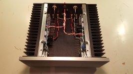
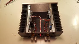
Had chance to get one stereo ACA version (march 2018 batch) at Diyaudiostore and it's now singing since 2 weeks at home...
Listening is very nice, very sweet... i find atmospheres, reverb and harmonics very well made.
The sound seems very rich.
Note that the output impedance, a little high, affects the frequency response and damping of the system, so be careful to pay attention to the speakers associated with it (as for tube amps)...
The ACA, for me, connected to complex impedance speakers that need current/power, won't compare to a well design high power amp (like some other Pass designs) but, it's not the way his creator meant to use it... i know
Maybe a little downside for the 19V ps supplied with the kit :
Mine have few hf filter residues audible in my 88dB/1W/1M speakers (little 16khz whistle i you put ears close to tweeters), i don't know if i'm the only to notice that.
This defect disappears if I use my personal laptop 19V power supply... nothing critical in short but be aware.
I had tests with a 24V linear supply I had in stock (1000VA transformer, 2 * 47000uF CRC filtering) and after re-setting bias according to the recommendations of NP :
It does not seem to me that the qualitative gain (if it exists) justifies the size and the cost of such a power supply, but perhaps, I say PERHAPS, ambiances, transparency and depth are a little better rendered.
More obvious in 24v are the gain of spl reachable and especially the decline of the distortion that comes a little later... very audible for me.
Many thanks to Nelson and the community for this amp !
It's really brillant to be able to share all of this, while been so far from each others in the same time
See you soon ! Fabien
Attachments
Just out of curiosity, is it possible to substitute Semisouth R100,125 etc for one or both IRF240 in the ACA?
I’m stuffing a 2014 1b pair of boards I found in the swap meet for sale...sort of along the way to building an F2J. I’ve managed to hoard a few extra Semisouth and was wondering if the same distortion improvements would be seen as is noted with the F2. Has Papa or anyone else tried it just for giggles?
I’m stuffing a 2014 1b pair of boards I found in the swap meet for sale...sort of along the way to building an F2J. I’ve managed to hoard a few extra Semisouth and was wondering if the same distortion improvements would be seen as is noted with the F2. Has Papa or anyone else tried it just for giggles?
I stand corrected, talking about C3 (input cap).
Do I calculate the cut-off frequency based on the 10K input impendance or did I over-simplify things ?
I am not an expert but I would say that it is the 332k R10 + approx 2.5k P1 in parallel with the input imedance of the JFET that causes roll off at the lower frequencies.....
I think you can assume that you have a generator at the C3, R11,R12 point when making the calculations......but I am on "thin ice".....
A 4.7 uF may work fine as with 10 uF it is only 0.5 dB down at 10 Hz.....according to the specification.
Best would be to try it and make some measurements.
Not many speakers goes below 25 Hz.....and small two-ways has not much energy below 40 Hz.
Hello,
I built somes aca for me and friends! Sound great! First time I built a A class amp.
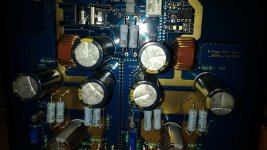
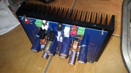
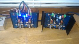
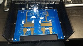
I made custom PCB based on aca design, have a look on the shematics (I add a silly design to reduce inrush current and an reverse polarity protection, silly design again because I use a comparator not the best design I did). The output caps are arranged in a such way that there is less 'pop' at on/off. I made a 2 channel pcb using a meanwell psu (30$ on ali express) with p1m connector, in fact exactly the same that Nelson told about for aca 1.5 stereo version (His choice confort me ).
I used kicad as ecad tool and seeedstudio as pcb manufacturer, other parts come from newark/digikey. I use bf862 smt version instead of expensive sk170 from linear. Also I add small filter for PSU, a self from wurth elektronik to create a common mode rejection PI filter to reduce meanwell psu output ripple @ 100khzand separate carrectly the two channels.
I test the beast with a high end system and I listening music with my not very good Cabasse 4R (corvette 301) speaker, result: wow! but I'm new in the high end music amp and have no very comparison experiences. This introduction to small class a amp gave me the virus, I think I'm beaten and I today work on my own version of class a amp!
I built somes aca for me and friends! Sound great! First time I built a A class amp.
I made custom PCB based on aca design, have a look on the shematics (I add a silly design to reduce inrush current and an reverse polarity protection, silly design again because I use a comparator not the best design I did). The output caps are arranged in a such way that there is less 'pop' at on/off. I made a 2 channel pcb using a meanwell psu (30$ on ali express) with p1m connector, in fact exactly the same that Nelson told about for aca 1.5 stereo version (His choice confort me
).I used kicad as ecad tool and seeedstudio as pcb manufacturer, other parts come from newark/digikey. I use bf862 smt version instead of expensive sk170 from linear. Also I add small filter for PSU, a self from wurth elektronik to create a common mode rejection PI filter to reduce meanwell psu output ripple @ 100khzand separate carrectly the two channels.
I test the beast with a high end system and I listening music with my not very good Cabasse 4R (corvette 301) speaker, result: wow! but I'm new in the high end music amp and have no very comparison experiences. This introduction to small class a amp gave me the virus, I think I'm beaten and I today work on my own version of class a amp!
Attachments
Hi Zen...by “lower position”, do you mean Q1?
I’ve attached the schematic for the “1b” board I came across at some point...although I don’t know where now.
I noted that the original value for R12 is still present in this “1b” schematic. I am wondering if I can just install the 39.2K value at R12 as well as the 2.21K for R15 regardless of what power supply I end up using?
I have a couple of 19 volt SMPS I picked up at Radio Shack when they closed down by me. I didn’t have much luck using them with a phono amp project as they were too noisy, although everything was too noisy with it except a battery supply so far. I’m not sure if they’ll be any better in this application.
My other option is to build a linear supply with what I have lying around. I could also build the F2J supply now based on the F1 guidelines and temporarily use it with the ACA. Last option would be to just order the new 24 V SMPS they are recommending for the new ACA.
I’m not 100% sure about trying the Semisouth here yet. I’d want to come up with a reversible situation, even if its just longer wires connecting to the transistors so they can be removed with minimal further heat exposure. At one point I was looking for a test socket to try and use to swap different transistors in and out of the F2 circuit.
Attachments
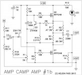
I noted that the original value for R12 is still present in this “1b” schematic. I am wondering if I can just install the 39.2K value at R12 as well as the 2.21K for R15 regardless of what power supply I end up using?
As i understand the design, R12 will set the gain, so going from 68k to 39k will lower the gain (cliping with 2.1vrms instead of 1vrms i think) and also reduce the output impedance to get the 10 damping factor with 8r speaker. So no link with your psu you can just replace r12 for 39k with a 19/24v psu no issue here. But adding r15 will set the current bias to 1.5 amp instead of less (don't remenber the value, i understand that r15 will reduce the viewed impedance by the ztx450 of the bridge composed with bigs resistors so the ztx 450 will drive more strong the upper mosfet) so your mosfet irfp240 will flow more current and then will produce less thd and be able to drive more strong your speaker but your psu will be more challenged so for a single channel you can count at least 50% more power from your psu (number not exact but this is the idea to understand what is r15).
Hello,
I built somes aca for me and friends! Sound great! First time I built a A class amp. <snip>
Great that you were inspired to DIY it!
Build looks good and nice to hear that you like the sound.
Congratulations!
- Home
- Amplifiers
- Pass Labs
- Amp Camp Amp - ACA