
RdsON is typically, the minmum resistance with a FET, with the gate slammed to 10V and the Vds will go almost to 0.0V. It is a parameter used for switching power supply design where you might have an inductor the FET and say 12V. You turn on the FET really hard and fast and current builds up in the inductor. Then you shut it off and the inductor still pulls current etc. etc. It might be analogous to Vcesat in a Bipolar.
It is not generally a parametor we care about because we operate in the resistive region between off and on.
Then there is Drain Resistance, that could actually be associated with RdsON but??? Then there is your load resistor on the drain???
It is not generally a parametor we care about because we operate in the resistive region between off and on.
Then there is Drain Resistance, that could actually be associated with RdsON but??? Then there is your load resistor on the drain???
Last edited:
I am confused by these statements
If it is "an active component with an AC negative resistance" how can it's contibution be higher impeadance? It's negative, simply speaking, thats lower.
The negative impedance of the mu follower is in parallel with the 8 ohm load. To see it's effect on gain, remember to gain is roughly RL/(1/Gm).
The parallel combination of 8 ohms in parallel with -16 ohms is 16 ohms. Since RL is higher, the gain is higher. Using the conductace formula for parallel resistors, 1/8 + 1/(-16) = 1/16.
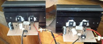
I built one channel using IRF640s, a 2N3904 and MPF102 (Idss=11mA). The only deviation from the ACA1 schematic was a 0.1 ohm resistor in series with the source of Q1. To measure open loop gain I just look at the gate of Q4 with a scope. Gain was 20 (26dB) with the 0.1 in place and 23.1 (27dB) with the 0.1 bypassed.
Looking at the IRF data sheet, the Gm is very non-linear at 1 amp. Isn't there a better part? This amp biases Q1 pretty hot, but that makes it more linear.
Open loop gain vs distortion tradeoff
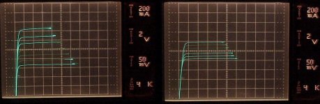
I looked at an IRF640 on the curve tracer using offset to get smaller steps around the (about) 1 Amp operating point. The second plot is the same part with 0.47 Ohms inserted in the source lead. The gain goes down but the linearity increases. I have no control over the camera shutter speed so some of the traces are fading out.
I replaced the MPF102 I was using with a PN4393. It gave slightly lower distortion numbers. Then I installed a 0.47 Ohm resistor between the Q1 source and ground and ran distortion plots with and without the source resistor. The distortion is higher above 4 Watts because of clipping, but at lower levels the distortion is lower inspite of the fact that the open loop gain is lower. Open loop gain measured 29.3 dB with the 0.47 shorted and 23.2 dB with the 0.47 enabled. DC operating point was adjusted to 10V at idle for each test.
Square wave response of the amp is very well behaved.
Attachments
Well here we are!
MAKE | My Day at Amp Camp
http://blog.makezine.com/2012/07/20/my-day-at-amp-camp/#jp-carousel-224348
MAKE | MAKE magazine
Loudthud, that circuit is quite recognizable! Even with the monster resistors!
MAKE | My Day at Amp Camp
http://blog.makezine.com/2012/07/20/my-day-at-amp-camp/#jp-carousel-224348
MAKE | MAKE magazine
Loudthud, that circuit is quite recognizable! Even with the monster resistors!
Last edited:
1) I wouldn't assume too much, as it depends on everything. There
generally will be a sweet spot where the 2nd nulls and where the total THD
is lowest, and on either side of that the 2nd comes back.
That was in reference to a question about R1, R2, R3, R4 and their ratios. (I'll just refer to them as R1 and R3.) I made a resistor string with a 0.12 ohm on each end and six 0.05 ohm resistors in between. Total resistance 0.54 ohms. The first attachment shows distortion plots. The comments are the two resistor values in order R1, R3. The surprising thing was that the lowest distortion was when R1 was zero! Looking at the analyzer output though, there was a lot of 3rd and higher harmonics. At any other position the distortion is a nice sinewave at 2x the frequency up to about 4 watts. (I didn't try R3 = 0.0 ohms.)
To investigate this I re-arranged the resistors so that all the 0.05 ohmers were on the Q2 source end and plotted three more curves in the second attachment. The third attachment is the same as the second but with three more curves with the 0.47 ohm resistor between the Q1 source and ground.
Attachments
Just a side note on one of the required parts
I’ve just notice something strange Mouser (Mouser Electronics - Electronic Components Distributor), there sort of like another Digikey, has 6,793 units of the 2SK170-GR(F) in stock. They have zero of the 2SK170-BLF in stock but they have 29,600 on-order of which they will receive 8,998 by 8/20/2012 and another 13,600 by 11/9/2012 (at least according to their web site). They don’t have any of the p-type and have no plans to get any in. The manufacturer is Toshiba.
At first this seemed like good news, but then I got to thinking (fair warning I have a devious mind). Obviously Toshiba is not going to magically look under some table in there stock room and find these JFets sitting around in three month increments. Have they started up production again? I doubt Mouser got a really good deal on e-bay. And besides Linear Systems a much smaller fish has taken up the torch producing drop in replacements with the LSK170. They would have less competition in the p-type domain, however it would be a strange situation where one company makes one half of a complimentary pair and another makes the other side but it would still be excellent for the industry as well as DIY.
My guess (only my speculation) is Toshiba made a really big mistake discontinuing 2SK170 and 2SJ74. This is being shown up by Linear Systems filling in the gap in the market. What to do to avoid getting chastised by your shareholders? Leak quantities of the 2SK170 and drive Linear Systems out of business, then point to them and say we were right to discontinue those old JFets nobody wants or needs anymore. The 2SK170 sells for $0.48 in units of 250 and the LSK170 sells for $0.50 in units of 1,000. So if quantities of 2SK170 magically continue to appear market forces will make this inevitable.
Strange I’m normally not the conspiracy theorist type.
My guess (only my speculation) is Toshiba made a really big mistake discontinuing 2SK170 and 2SJ74.
ah, not even dust in their pockets
btw, did Toshiba actually make the devices themselves
The 2SK170 sells for $0.48 in units of 250 and the LSK170 sells for $0.50 in units of 1,000.
Get 'em while you can.
Your calculations would be correct if Q2 was a constant current source, but it's not.
Note how C2 is connected to the bottom of R3/R4. When Q1 increases it's current to pull the load negative, the voltage drop across R3/R4 increases, C2 couples this change to the gate of Q2 making it conduct less. Q3 also conducts more which reduces the Q2 gate voltage. When Q1 reduces current, the voltage drop across R3/R4 reduces. C2 couples this positive going voltage to the gate of Q2 making it conduct more. Q3 also sees this voltage drop, it conducts less until the current flow through R1/R2 and to the load increases to makeup the difference in voltage from the source of Q2 to the drain of Q1.
If Q2 was a constant current source and the bias was 1 Amp, Q1's current could go up to 2 Amps or down to zero Amps supplying +/- 1 Amp peak to the load. Because Q2's current changes to be the opposite of Q1, the load current could be +/- 2 Amps in theory. However, Q1 would be very non-linear, although distortion would be mostly even order. In this design, with an 8 ohm load, the amp runs out of voltage before it reaches +/- 2 Amps load current. Idle current could be reduced, but distortion would increase.
Ok, I've got the parts kits all bundled up and I'm really proud of them. They'll have everything required to make a functioning amp, including wire! Jason, diyFounder, was in town and helped out on some of the packaging. Of course we forgot a few things and are ordering them. The boards should arrive soon, I hope this week and will be added to the kits. Tragically I'm leaving town in a couple of days until the 14th of August. So within a month kids, can't do anything until the boards arrive.
Mark
Mark
- Home
- Amplifiers
- Pass Labs
- Amp Camp Amp - ACA