Hi All,
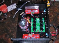
Almost finished with my first F5. Spent over 4 hours listening to it last night. It sounds great! Much more detail than the tube amp I've been using for the last four years. It's like a vail has been removed from the music. Soundstage is much more detailed and precise. Bass is much more controlled. Which makes sense considering the drastic increase in damping factor. My tube amp has on output impedence of 4.5 Ohm so really bad damping factor.
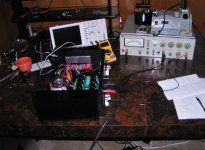
My build seems to be performing as expected. Gain is 15.4db. I wanted to check THD but alas it is lower than what my old HP distortion analyzer can measure. Measuring the internal oscillator I am starting out at 0.0068%. Higher than the 0.002% Mr Pass mentions for the F5. I took some measurements at different wattage ratings anyway but there are some inconsistencies in the numbers and nothing to really say the F5 is anything other than <0.002%. The only thing I saw is one channel seems to have slightly higher distortion than the other. Odd think is the one with higher distortion is biased slightly lower than the other.
Currently I'm running only around 1 amp of current but will increase to 1.3 after I replace the R11/12 and re-bias. I did a stupid thing of not zero-ing the trim pots before powering on and beginning biasing. They were set to around 2k Ohm so I was probably running around 2 amps for a short while. The resistors turned a bit brown so I ordered some replacements. Everything else seems to have survived the abuse OK.
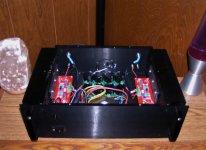
My heat sinks only reach ~42 degrees C when things stabilize so things seem OK there. I do wonder how things will fare with the case top installed. This case has no venting which I didn't think about earlier. Does anyone think this will be a problem? I just now turned the unit on with the case top in place and a temperature probe inside. I'll report back where it ends up. I would think it would be the same as my heat sink measurement but that was with the top off, so maybe it will be higher too.
I'm currently missing the 0.0033uf cap across the mains input indicated in the PSU schematic. I have one on order now though. Can someone tell me the function of this cap? Is it a high freq filter by any chance?
Anyway I'd like to thank Mr Pass and all of you diy'ers who share your knowledge and experience. As it was I spent many months researching and gathering parts and can't imagine how long that would have taken without all of your help (unwitting, and otherwise).
Sorry for the fuzzy pictures, my wife's out of town with the good camera.
Almost finished with my first F5. Spent over 4 hours listening to it last night. It sounds great! Much more detail than the tube amp I've been using for the last four years. It's like a vail has been removed from the music. Soundstage is much more detailed and precise. Bass is much more controlled. Which makes sense considering the drastic increase in damping factor. My tube amp has on output impedence of 4.5 Ohm so really bad damping factor.
My build seems to be performing as expected. Gain is 15.4db. I wanted to check THD but alas it is lower than what my old HP distortion analyzer can measure. Measuring the internal oscillator I am starting out at 0.0068%. Higher than the 0.002% Mr Pass mentions for the F5. I took some measurements at different wattage ratings anyway but there are some inconsistencies in the numbers and nothing to really say the F5 is anything other than <0.002%. The only thing I saw is one channel seems to have slightly higher distortion than the other. Odd think is the one with higher distortion is biased slightly lower than the other.
Currently I'm running only around 1 amp of current but will increase to 1.3 after I replace the R11/12 and re-bias. I did a stupid thing of not zero-ing the trim pots before powering on and beginning biasing. They were set to around 2k Ohm so I was probably running around 2 amps for a short while. The resistors turned a bit brown so I ordered some replacements. Everything else seems to have survived the abuse OK.
My heat sinks only reach ~42 degrees C when things stabilize so things seem OK there. I do wonder how things will fare with the case top installed. This case has no venting which I didn't think about earlier. Does anyone think this will be a problem? I just now turned the unit on with the case top in place and a temperature probe inside. I'll report back where it ends up. I would think it would be the same as my heat sink measurement but that was with the top off, so maybe it will be higher too.
I'm currently missing the 0.0033uf cap across the mains input indicated in the PSU schematic. I have one on order now though. Can someone tell me the function of this cap? Is it a high freq filter by any chance?
Anyway I'd like to thank Mr Pass and all of you diy'ers who share your knowledge and experience. As it was I spent many months researching and gathering parts and can't imagine how long that would have taken without all of your help (unwitting, and otherwise).
Sorry for the fuzzy pictures, my wife's out of town with the good camera.
Attachments
you need vents on both bottom and top
Thanks for your input. As much as I don't want to take everything apart again I believe you're right. Looking at my layout can you make a suggestion of the best way to add them? I can only think of drilling many holes on the drill press. Or, maybe cutting out some openings with a coping saw or a nibbler and attaching a metal screen over them.
Thanks in advance for any suggestions
For the top, I just "spacered" mine so it floats about 1/2 high...1/2 space all the way around ventilates well. At least for the top.
Russellc
i gues this is a par-metal chassis?
Yes, that's right.
It's ironic, I used one of their chassis for my passive pre-amp which has no active components.....and it has major ventilation on top and bottom...just to let dust in on my expensive auto-former attenuators

Par-metal will machine vents in the covers upon request for no additional charge. A least it was that way when I ordered a case for a headphone amp I built.
Yes, I agree. They were selling this one on ebay and I didn't think to ask them to modify it.
thanks
In thinking about it I suppose the source resistors I browned must have been pulling quite a bit more than the 2 amps I mentioned earlier. Anyway, I replaced them and everything seems perfect now. I biased to ~1.3 amps and get a much closer voltage reading on the v+ and v- resistors when output is close to zero volts.
I also had vented bottom and top panels made so now get to completely take everything apart again while I re-drill all the mounting holes in the bottom.
I also had vented bottom and top panels made so now get to completely take everything apart again while I re-drill all the mounting holes in the bottom.
your on your way to extecy
this is a realy nice sounding amp.
I'm already there. I've been listening to the amp for over a week now. I just run it with the top off.
Sounds great!, as you say.
At this point the only thing else I want to change is reducing the PS ripple. I can hear it slightly from my listening chair. My scope says ~90mv RMS on both rails and the output if I remember correctly. I only have 40000uf on each rail. From my spice model, which only shows ~60mv RMS, changing to 60000 should reduce the ripple almost in half. I realize this will increase inrush current etc. but hope this 50%, increase won't cause any real problems I have to deal with.
Does anyones see any problems with my thinking to change my ps caps from 8 10000 to 8 15000 ?
no problemo , at least not major ones
if you observe mech buzz from xformer or some additional warming , just buy another identical one , rearrange da bloody thing in dual mono , and voila !
Thanks Zen. xformer is mechanically silient (unlike the one in my tube amp which is very loud). I probably just got lucky with it from what I've read in some other posts. Or, i'm just not pushing it hard, which is OK.
cheers
it is allways a good thing with oversized transformer i guess you have some sort of softstart? then the inrush won't be a problem. i have 225VA and 6x12000uF pr ch.
so 450VA 144.000uF.
with 2xCL-60 in series as softstart. bypassed by relè.
i also used the same softstart on 1000VA 440.000uF.
i guess you have some sort of softstart? then the inrush won't be a problem. i have 225VA and 6x12000uF pr ch.so 450VA 144.000uF.
with 2xCL-60 in series as softstart. bypassed by relè.
i also used the same softstart on 1000VA 440.000uF.
it is allways a good thing with oversized transformer
so 450VA 144.000uF.
with 2xCL-60 in series as softstart. bypassed by relè.
i also used the same softstart on 1000VA 440.000uF.
My PS is a bit smaller than yours and is shared between the channels. I think i'm going to take some time and do some research before simply increasing the size of my caps and make sure I don't want make some bigger upgrade, like dual supplies for example.
One thing you mention that sounds interesting is the relay bypass on the CL-60's. Mine are in series all the time and generate lots of heat. Seems like a waste to me. Can you tell me the reason you think it was good to bypass them? They seem to be made to operate this way so just wondering if there is some angle I am missing, besides heat.
- Status
- This old topic is closed. If you want to reopen this topic, contact a moderator using the "Report Post" button.
- Home
- Amplifiers
- Pass Labs
- Fresh F5 Build