There is a sympatic guy in Croatio who offers nive PCB for some Aleph projects (http://web.vip.hr/pcb-design.vip/index.html).
He proposes a PCB of a Zen Balanced (power) amp, for which I couldn't fine any info or thread (yes I searched, but it would take a week before going tru all the threads...).
Actually I'm interested in this one because... the PCB size fits in the case that I want to use (an old french-made Cairn K3 Mosfet amp, which sounds like sh..), it has huge heatsinks and is perfect for a DIY'er who is too lazy to build its own case (and it looks nice, beside that ).
Pass' website doesn't give any info for that beast.
Has anybody built it?
Thanks,
- dan
He proposes a PCB of a Zen Balanced (power) amp, for which I couldn't fine any info or thread (yes I searched, but it would take a week before going tru all the threads...).
Actually I'm interested in this one because... the PCB size fits in the case that I want to use (an old french-made Cairn K3 Mosfet amp, which sounds like sh..), it has huge heatsinks and is perfect for a DIY'er who is too lazy to build its own case
(and it looks nice, beside that ).Pass' website doesn't give any info for that beast.
Has anybody built it?
Thanks,
- dan
")
BZLS Cap
I am making my Balanced Zen Line Stage PCB now. In the article, Nelson suggest using 100+ Volt rating capacitors. I have both 1500uf/160V cap and 3300uf/63V on hand. If I use the latter one, will it works OK? or should stick on the higher volt rating one? (I like to pick the latter for better smooth out the ripple effect!)
Any suggestion?
Thomas
63 volts caps vs. 160volts
Unlike film (plastic) capacitors, anelectrolytic caps increase its lossfactor with its voltage capacity. Means qualitywise you better use the 63V caps, but note that the voltage in the Balanced Line Stage PS is about 80V after the rectifier!
You may use them after regulation, where the voltage is about "only" 60V per rail.
- dan
I have both 1500uf/160V cap and 3300uf/63V on hand. If I use the latter one, will it works OK? or should stick on the higher volt rating one?
Unlike film (plastic) capacitors, anelectrolytic caps increase its lossfactor with its voltage capacity. Means qualitywise you better use the 63V caps, but note that the voltage in the Balanced Line Stage PS is about 80V after the rectifier!
You may use them after regulation, where the voltage is about "only" 60V per rail.
- dan
Re: 63 volts caps vs. 160volts
isn't it the other way around? -loss decreases with voltage rating?
Alfetta87 said:
Unlike film (plastic) capacitors, anelectrolytic caps increase its lossfactor with its voltage capacity.
- dan
isn't it the other way around? -loss decreases with voltage rating?
Lossfactor in caps
No, Electrolytics increase their Lossfactor with the voltage increase. Film caps decrease[/] their lossfactor with the voltage increase.
- dan
isn't it the other way around? -loss decreases with voltage rating?
No, Electrolytics increase their Lossfactor with the voltage increase. Film caps decrease[/] their lossfactor with the voltage increase.
- dan
Lossfactor in caps -2-
We have to relativilize this though: a cap from a same manufacturer in a given capacitance and a voltage of f.e. 63V has a better lossfactor than the same capacitance (and construction) than a 100V or 160V. In a case of two different types (brand, construction, size...) you have to check from the manufacturer's datasheet which one is better.
Note: a cap with lower loss factor (and ESR) will heat up less at its limit of voltage than a worse lossfactor, means can be driven harder to its limit.
Connect and touch it, if it heats up too much, change them. They will not blow away immediately. But wear some protection glasses though, you never know...
- dan
No, Electrolytics increase their Lossfactor with the voltage increase. Film caps decrease[/] their lossfactor with the voltage increase.
What is this "lossfactor" you speak of called in the datasheet of a capacitator? Just curious...
For instance the Panasonic FC series have the following data:
Rated voltage 6.3 10 16 25 35 50 63 100
Tan d 0.22 0.19 0.16 0.14 0.12 0.10 0.08 0.07
The ESR for the value 470 uF for the same brand of caps :
Rated voltage, ESR:
6.3, 0.117
10, 0.117
16, 0.09
25, 0.068
35, 0.052
and so on.
Alfetta87 said:He proposes a PCB of a Zen Balanced (power) amp, for which I couldn't fine any info or thread (yes I searched, but it would take a week before going tru all the threads...).
Actually I'm interested in this one because... the PCB size fits in the case that I want to use (an old french-made Cairn K3 Mosfet amp, which sounds like sh..), it has huge heatsinks and is perfect for a DIY'er who is too lazy to build its own case
One simple and effective way to make a balanced amp is to use two amplifiers. The first amp is used just like normal. The second amp recieves the inverted signal of the balanced input. The first amp is connected to the + input of the speaker, and the second amp is connected to the - input of the speaker. This gives you a nice balanced/bridged amplifier with slightly lower distortion than a single ended amplifier. The only thing you might have to do is come up with some way of balancing the inputs if you are not using a balanced pre-amp.
Cheers,
Zach
how to test bzls main board
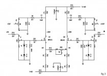
I have completed my Balanced Zen LS boards. So far, the PSU output is good at +60V and -59.7V according to the design. However, I blew the Main board once due to wrong wire! I think I have replaced the bad one; however, when I check each parts, I don't know what's best way to check the circuit w/o connecting the power.
For example, the Z1 and Z2 in the schematic. I use the multimeter diode test and they are both alive. However, I use switch to Ohm check and both channel's reading is different. One channel is 3 times the resistance than the other channel. Is my testing method correct? If not, how do I test the baord in the right way?
This is my first project and I am ME and Computer Science major. I am picking up my EE knowledge lost in college!
Thanks for all comments!
Attachments
- Status
- This old topic is closed. If you want to reopen this topic, contact a moderator using the "Report Post" button.
- Home
- Amplifiers
- Pass Labs
- Balanced Zen Amp info needed (not line stage)