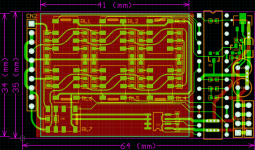
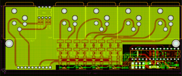
This is it, only 34 mm X 41 mm X 7mm, (little larger than a 9v battery, but, less than 1/2 the height), for the analog attenuator, another 23 mm for the processor outside the shield.
By manipulating the placement of resistors over the Rp#x & Rc#x, you can configure this PCB to do a 64 step balanced log attenuator, 1db per step starting at -64db, or double ended single unbalanced attenuator. It also can be configured for linear action.
RL7 is for an additional full mute. The shield is as thick as you would expect to see on TV tuner modules.
It draws 1ma for around 1 second during a switch in volume, then settles at around 0.004ma. RX runs at 3v cmos levels, 1200 baud, or, with a 25 cent photodiode, it will receive an IR signal up to 6 inches. It has 16 addressable IDs to allow multiple module controls from the same 1 com signal.
Front Panel Processor controler & display & long range IR remotecontrol board comming next week.
Attachments
Banned
Joined 2002
I'm getting quotes for the PCBs on Monday, or Tuesday.
They shouldn't be too expensive. It's the 0.1% 0805 resistors which will be the killer, unless you trim them yourself.
As for the processor board, if you want it, it will be a little narrower, but wider to accommodate the 4 digit display & long range IR receiver.
They shouldn't be too expensive. It's the 0.1% 0805 resistors which will be the killer, unless you trim them yourself.
As for the processor board, if you want it, it will be a little narrower, but wider to accommodate the 4 digit display & long range IR receiver.
Banned
Joined 2002
It should match very well with you aleph, espicially internally & configure the attenuator for a nice low 10kohm impedance.
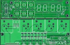
The processor board is only 1 PCB. Again, it was designed to work on low power, but, it can be powered by almost any power supply.
This 1 PCB has the display & IR remote control reciever & extended range regulated power supply. The attenuator module only works from 6v to 12v.
Read the processor capabilities here:
This 1 is a week old. Mainly, now, there is only 1 attenuator output since the new attenuator modules may be run in parallel.
http://pages.infinit.net/helloftp/attenprocessor.png
A few other little changes, but you should get the idea.
As for the remote, this module can learn keys from 1 of your existing remotes, which you may the use to control it, or, buy any cheap universal remote.
Brian Guralnick said:This is it, only 34 mm X 41 mm X 7mm, (little larger than a 9v battery, but, less than 1/2 the height), for the analog attenuator, another 23 mm for the processor outside the shield.
By manipulating the placement of resistors over the Rp#x & Rc#x, you can configure this PCB to do a 64 step balanced log attenuator, 1db per step starting at -64db, or double ended single unbalanced attenuator. It also can be configured for linear action.
RL7 is for an additional full mute. The shield is as thick as you would expect to see on TV tuner modules.
It draws 1ma for around 1 second during a switch in volume, then settles at around 0.004ma. RX runs at 3v cmos levels, 1200 baud, or, with a 25 cent photodiode, it will receive an IR signal up to 6 inches. It has 16 addressable IDs to allow multiple module controls from the same 1 com signal.
Front Panel Processor controler & display & long range IR remotecontrol board comming next week.
Very well done. Chapeau!
Jan Didden
Banned
Joined 2002
Not there yet, coming next week. Just finished part selection. I still need to proof the attenuator PCB on the weekend. I also just begun the schematic for the processor PCB. The attenuator module took more time than I though it would, but, the processor PCB is a simple layout by comparison. I don't have to worry about strict fit & nicely layed out equally spaced resistor / relay matrix, without 1 single via in there.
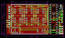
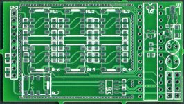
And, don’t forget the nice arched traces without 45, or, 90 degree edges. Also, the traces only enter and exit the SMD pads through the center, or perfectly through the corners. The audio traces also do not go under the middle of the resistors, which can lead to HF leakage, or crosstalk. (This helps alleviate some magnetic issues with metal film resistors, but not completely.)
And, don’t forget the nice arched traces without 45, or, 90 degree edges. Also, the traces only enter and exit the SMD pads through the center, or perfectly through the corners. The audio traces also do not go under the middle of the resistors, which can lead to HF leakage, or crosstalk. (This helps alleviate some magnetic issues with metal film resistors, but not completely.)
Re: Re: battery powered, balanced log attenuator pcb!
Thank you, I'll take a bow.
janneman said:
Very well done. Chapeau!
Jan Didden
Thank you, I'll take a bow.
")

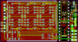
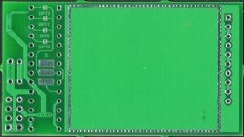
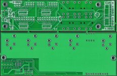
Here is the line source selector pcb.
Line switcher pcb. 4 balanced in, 1 out. Connector ready to mate with my attenuator.
Consumes so little power that it can be powered by battery, AC, or, PC RS232 serial port, or mini solar panels.
It can be controlled by the Minipanel board, or, PC RS232.
It has 16 ID addresses, so, 16 different units may be individually addressed on 1 RS232 port.
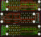
The design may be changed to a stereo unbalanced, or NTSC, or S-Video just by changing the connectors. The design may also easily be expanded to 7 inputs instead of 4. Running 2 in parallel, it can switch computer RGB-Comp, or SOG video, 3 in parallel for RGB/H/V video.
Line switcher pcb. 4 balanced in, 1 out. Connector ready to mate with my attenuator.
Consumes so little power that it can be powered by battery, AC, or, PC RS232 serial port, or mini solar panels.
It can be controlled by the Minipanel board, or, PC RS232.
It has 16 ID addresses, so, 16 different units may be individually addressed on 1 RS232 port.
The design may be changed to a stereo unbalanced, or NTSC, or S-Video just by changing the connectors. The design may also easily be expanded to 7 inputs instead of 4. Running 2 in parallel, it can switch computer RGB-Comp, or SOG video, 3 in parallel for RGB/H/V video.
Attachments
- Status
- This old topic is closed. If you want to reopen this topic, contact a moderator using the "Report Post" button.
- Home
- Amplifiers
- Pass Labs
- battery powered, balanced log attenuator pcb!