I need to connect the signal input wire and ground wire to the RCA plug and am on an iPhone without PCB schematic. Im staring at these two wires and know for certain one is input signal and the other ground...im just not sure which is which. One wire is soldered to the board adjacent to V- input and mid size elytic cap...I think this should run to the RCA connector ground but want to confirm?
The other wire (which I think is the signal input wire) lands on the middle of the board adjacent to the biggest cap, also flanked by small resistors and the smallest of the four transistors. I assume this is the positive for signal input?
The other wire (which I think is the signal input wire) lands on the middle of the board adjacent to the biggest cap, also flanked by small resistors and the smallest of the four transistors. I assume this is the positive for signal input?
Last edited:
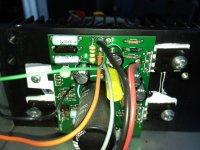
Thanks Nelson. Pic of one channel of the F3 is attached....
Green wire lands on PCB in top-middle of pic near the thick orange wire (signal out to the speaker terminal).
The thin black wire is in left-middle of pic to the left of the big black cap and also just above a few small resistors. Since there are more than one black wire...just to be clear its the thin black one flanked above by the green wire and flanked below by the orange wire.
Attachments
Looks like a Zen 9 board. See attached.
I don't know your board, but it looks like the black wire closest to the jfet is actually the input.
The green wire is a ground point. I assume this because the large black wire at the top of the photo is close to the Voltage in.
In the PDF below, there are a couple of ground points in that area.
My advice is to take the large ground and send it to an isolated point (not on metal) and begin a star ground. Remove the input ground at the board.
From the RCA input, run a ground to the star ground. Do the same for the speaker ground. Run a single thick wire to a CL-60 thermistor and attach it to a post on the metal chassis. (Clean the metal around the post. You can make a post with an inch long screw and nut. Use two nuts and a locking washer to lock it down.)
Do the same thing for the second channel. Only ground connection points for both channels is after the CL-60 thermistors. Not before!
Finally, run another thick wire from the post to the earth ground on the mains voltage input.
If anyone disagrees, please speak up.
Built my Zen 9 this way and it was dead silent.
No noise at speaker. None!
BTW- that heat sink looks tiny! Hope it's longer than it is high. This amp get hot!
Good luck!
Vince
Attachments
Last edited:
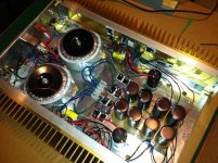
Here's mine. Ya-Ba!! Nice looking right?
See the the star ground? It's near the last power supply capacitor at either side of the capacitor bank. Don't do what I did!
Place your star ground closer to the middle of the amp as possible to shorten every possible path. Keep them away from transformers, if possibe. The 0v off the power supply ties into the star ground.
A good star ground point is usually at the 0v on the capacitor bank.
There are good examples out there, just look through previous build photos on this site.
GL!
Vince
Attachments
Last edited:
Thanks Vince and TP147...much appreciated!
Your feedback mirrors my intuitive guess...thanks for the confirmation...I soldered it that way last night and crossed my figures that I would not have to wake up this morning only to have to reverse the wires based upon your feedback.
Vince, thanks very much for offering the star ground scheme as a way to improve the amp further.
As far as that heatsink size, the two sides of the chassis ARE the heatsinks. The heatsinks must be 10-12" long? I hope this is not too small of HS?
Sorry about that. Your board does look a lot like the Zen 9. I thought the F3 had more parts.
After an hour or so, if you can hold your hand on the heat sink for 5 seconds, its about 55 degrees Celsius. Less than 5 seconds, it higher and that's not good for longevity. Get a fan on it. Any air movement over the heat sinks is good.
Have fun. Its a great amp.
Vince
After an hour or so, if you can hold your hand on the heat sink for 5 seconds, its about 55 degrees Celsius. Less than 5 seconds, it higher and that's not good for longevity. Get a fan on it. Any air movement over the heat sinks is good.
Have fun. Its a great amp.
Vince
Hi Mike,
Q2 & Q3 produces most of the heat because of ther dissipation of 29W/36W.
So it was a good idea to mount them on the bottom end of the HS.
But if the HS is 12" long why didn't you mount the board more to the middle of th HS?
Also a good idea is to mount the rect diodes to the outer HS, because if you use soft recover diodes as I did there is a voltage of 1.2V and current > 1,5 A so you also have here a disspation arround 3 W for each diode and with 8 diodes there will be 24W. Here is my biggest heating problem.
Edit: Your 220µF caps seems to be quite small. May be a visual illusion, but which voltage rating do they have. C5, C6 and C7 must be 50 V at min.
cheers
Thorsten
Last edited:
Hi Mike,
Q2 & Q3 produces most of the heat because of ther dissipation of 29W/36W.
So it was a good idea to mount them on the bottom end of the HS.
But if the HS is 12" long why didn't you mount the board more to the middle of th HS?
Also a good idea is to mount the rect diodes to the outer HS, because if you use soft recover diodes as I did there is a voltage of 1.2V and current > 1,5 A so you also have here a disspation arround 3 W for each diode and with 8 diodes there will be 24W. Here is my biggest heating problem.
Edit: Your 220µF caps seems to be quite small. May be a visual illusion, but which voltage rating do they have. C5, C6 and C7 must be 50 V at min.
cheers
Thorsten
Thanks Thorsten for the queries on minimum cap voltages and layout. I had to wait until the weekend to check these things. The 220uF caps are all rated 50V.
I did not build this amp...but I could change things if helpful. The heatsinks are 10 inches long. You are correct in that they are not centered. I'm not sure if this is because the builder desired to have distance between the boards and the transformer? The boards are closer to the bank of filter caps and the chassis with the speaker terminals.
I see your point about externally mounting the diodes but I have twin 4 yr olds that like to touch everything!
Thanks for the tips.
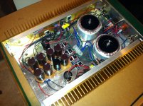
hi here is a pic of my F3:
It is only a 2HE case with 80mmm heigh.
The FFETs are all mounted to the inner heat sinks, Q2 and Q3 right in the corner to the outer heatsinks.
The coupling from inner to outer HS works well. With environment temperature of 20° C the inner HS is arround 48°C with Cover on top. If Environment is above 24 °C I lift of the Cover. Outer HS is always 3-4° C lower.
Don't bother with the amps near the transformer. My boards are quite near to the transformer and the F3 doesn't make any noise with no signal.
The rect diodes are mountet to the small inner HS you can see in the center of the case. With high environment temperature an cover on top th HS is arround 55° C and inside the head of the inbus screw is arround 10° C higher!
If your kids touching the _hot_ amp, they would do it only once. It will not cause heavy pain, but they will understand what is meant by hot.
cheers
Thorsten
An externally hosted image should be here but it was not working when we last tested it.
It is only a 2HE case with 80mmm heigh.
The FFETs are all mounted to the inner heat sinks, Q2 and Q3 right in the corner to the outer heatsinks.
The coupling from inner to outer HS works well. With environment temperature of 20° C the inner HS is arround 48°C with Cover on top. If Environment is above 24 °C I lift of the Cover. Outer HS is always 3-4° C lower.
Don't bother with the amps near the transformer. My boards are quite near to the transformer and the F3 doesn't make any noise with no signal.
The rect diodes are mountet to the small inner HS you can see in the center of the case. With high environment temperature an cover on top th HS is arround 55° C and inside the head of the inbus screw is arround 10° C higher!
If your kids touching the _hot_ amp, they would do it only once. It will not cause heavy pain, but they will understand what is meant by hot.
cheers
Thorsten
Last edited:
- Status
- This old topic is closed. If you want to reopen this topic, contact a moderator using the "Report Post" button.
- Home
- Amplifiers
- Pass Labs
- Quick direction please for Firstwatt F3 DIY