Hi,
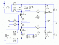
never heard about F5 with BJT input until Lazy Cat published his TSSA.Other DIY member Juma had his own way to do F5 with BJT input too. (atached picture)
or post #14 www.diyaudio.com/forums/solid-state/210116-tssa-simplest-symmetrical-amplifier-2.html
DIY member Jay said between these two Juma's version simulated better distortion wise-typical F5 topology.Also he thinks that BJT MAY sound better than JFET in this place.
Having this information i built Juma's F5 one test channel.And it's amazing.So lively and punchy on bass.I think everyone should try it, at least those who dont have quite hard to get JFETs or those who want to experiment.Schematic is very similar to org F5 (with little changes same PCB can be used)
Personally i've never heard original F5 in my system ,so better,worse or how different is BJT versus JFET at input this is the question we will need to answer in this thread.
Attachments
Daudio25 asked me some questions through PM and I suggested we can discuss them here:
1.EUVL found 2sk1529/2sj200 to be better than IRFP HEXFETs (you can search for data in this forum's section). They have lower Vgs so nothing should be changed, you'll just have to readjust the bias after changing the output devices.
My choice was 2sk2013/2sj313. The thread about it is here:
http://www.diyaudio.com/forums/pass-labs/168040-f5-2sk2013-2sj313.html
The same thing goes here too - after changing the output stage, readjust the bias.
2. I like BJT-input version too ...
3. I designed the BJT-input version with same gain as original - gain is set by 750R/150R feedback network which gives same ratio as the original does (50R/10R). So it's not the amp that is louder but it seems that you have capable signal source and/or efficient speakers.
1.i have 2sk1529/2sj200 mosfets. It's worth to change IRFP? If so , what do i need to change in schematics?
2.How You compare it to origininal F5? Yours BJT is better? distortion which is lower?
3.Standart FET F5 have little gain.With BJT i can drive my speaker very hard.Maybe BJT have more gain?
1.EUVL found 2sk1529/2sj200 to be better than IRFP HEXFETs (you can search for data in this forum's section). They have lower Vgs so nothing should be changed, you'll just have to readjust the bias after changing the output devices.
My choice was 2sk2013/2sj313. The thread about it is here:
http://www.diyaudio.com/forums/pass-labs/168040-f5-2sk2013-2sj313.html
The same thing goes here too - after changing the output stage, readjust the bias.
2. I like BJT-input version too ...
3. I designed the BJT-input version with same gain as original - gain is set by 750R/150R feedback network which gives same ratio as the original does (50R/10R). So it's not the amp that is louder but it seems that you have capable signal source and/or efficient speakers.
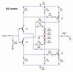
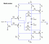
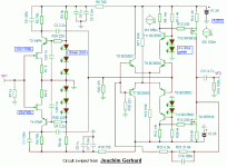
There was also some discussion of F5 with alternate input devices in Greg's thread here. Some of those ideas got recycled here, in between Joachim's designs.never heard about F5 with BJT input until Lazy Cat published his TSSA.Other DIY member Juma had his own way to do F5 with BJT input too.
IMHO, your bias method (similar to second pic below) is good for MOSFET input devices as the input stage idling current is almost independent of Vgs. OTOH, I think I prefer the LED biasing arrangement in pic one for BJTs, as it gets rid of the capacitors.
The second half of Joachim's circuit (3'rd pic below) looks like a nice solution as well.
Attachments
Hi
I have experimented with circuit in post #1 with 2SK1530/2SJ201 (one pair). However, I have 0.33 ohms source resistors and a gain of 10. It is biased at about 600ma on my bench. The damping factor I obtain is only 4 is that expected? I remember that the DF of the original F5 was a lot higher than that....The gm of the mosfet I use is supposed to be similar to the IRFP... or do I have fake mosfets with muche lower GM
Thanks
Fab
I have experimented with circuit in post #1 with 2SK1530/2SJ201 (one pair). However, I have 0.33 ohms source resistors and a gain of 10. It is biased at about 600ma on my bench. The damping factor I obtain is only 4
Thanks
Fab
Hi fab !
Yes, that's to be expected because the OLG is much lower this way (input pair is strongly degenerated) which makes the GNFB also much lower and that's the cause of relatively high Zout i.e. low DF. Also, Toshiba MOSFETs have lover gm than IRFs (that lowers the DF too) but they are more linear so it seems like a fair trade.
I found that I like how it sounds, but if you want to significantly increase the DF (about 10 times) this is what you should change (sch. from post #1 of this thread):
- R14,R15 = 3k9 0.5W
- R4, R5 = 22R 0.5W
- R11,R12 = 220R 2W
- C1,C2 = 4700uF 6.3V
- remove R2,R3 in order to extend the range of bias adjustment
- Increase the bias current to 1A or so - more Id -> more gm (Yfs)
This way the gain will be about 20dB - if you want to lower it to standard F5 gain value, increase the value of R4,R5 to 43R.
Last edited:
Hi Juma !Hi fab !
Yes, that's to be expected because the OLG is much lower this way (input pair is strongly degenerated) which makes the GNFB also much lower and that's the cause of relatively high Zout i.e. low DF. Also, Toshiba MOSFETs have lover gm than IRFs (that lowers the DF too) but they are more linear so it seems like a fair trade.
I found that I like how it sounds, but if you want to significantly increase the DF (about 10 times) this is what you should change (sch. from post #1 of this thread):
- R14,R15 = 3k9 0.5W
- R4, R5 = 22R 0.5W
- R11,R12 = 220R 2W
- C1,C2 = 4700uF 6.3V
- remove R2,R3 in order to extend the range of bias adjustment
- Increase the bias current to 1A or so - more Id -> more gm (Yfs)
This way the gain will be about 20dB - if you want to lower it to standard F5 gain value, increase the value of R4,R5 to 43R.
What you suggest above is what I have tried but only in simulation ( before doing physical change on my board ). I wanted to first confirm that my MOSFET were not fakes. Second I wanted to know if there was something I have overlooked on his the design works ( I know it is a very low OLG). According to my simulation I could get a DF of about 6 times more ( you indicate 10 but Rie of input BJT is not 0...). But it would be still low....
The trade off that I am not so comfortable in the value changes you suggest is to reduce the drive current for the MOSFET ( R14/R15). ..
I will try again increasing the bias current on mosfets but I remember that it also reduced the max output swing of the amp ( Rds * Id)...
I thought also about reducing the CLG to increase the feedback factor thus increasing the DF but I do not have preamps with lots of gain...
However, you indicate that even with this low damping it sonds good...I suppose better than the original F5....
The concern I have is that I want an amp punchy on the bass...
Should I continue with this project?
Thanks
Fab
Last edited:
High DF is only indicating a high OLG and High GNFB - I never did listen to an amp with spectacularly high DF that sounded really good.
I even don't consider the DF as an amp's property that one should care about - it's Zout that imposes some practical limitations in the relationship between an amp and the speaker, and the Zout of about 1R is approximately the highest number that I feel comfortable with and the 0R1 is the value where, IME, the law of diminishing returns starts to kick in.
As I see it, the myth of DF is generated by hifi industry and hifi magazines in order to boost sales by announcing "another world-changing great revelation" (in other words, another pile of crap).
Of course, there are some very low Z speakers that need special care in this regard but still, it often happened that those kind of speakers sounded better with low DF amps than with some high DF amps.
Shortly, DF alone is not a deal-breaker, it's easy to test this circuit and see for yourself if it works OK for you - for me it did, although two of my speakers go as low as 3.5R impedance wise.
Thanks for yours comments 
Since my speakers are 4 ohms nominal and I do not know how low they can get , I will target an amp output impedance of 0,5 ohms or better. That means going from 2 ohms to 0,5 using some changes you have suggested..
By the way, it is this circuit and your "F5 meets Buzquito " amp that made me design my "F5-Juma with BJT input " which was later called " VSSA " by Lazycat. Lazycat and I had the same idea at the same time but he made it commercialized on his side....My version was also different since it used MOSFET for VAS as à good option you had pointed to us at the time.... Since then I have built the "VSSA Lazycat" version by curiosity but I think I prefer mine with MOSFET VAS...
So this project here and now is a trial to make a simplification of "vssa" which could be called " USSA" .... Ultra simple Symetrical amp I think that the name alone is appealing for success ...if the sound is good of course.
Fab
Since my speakers are 4 ohms nominal and I do not know how low they can get , I will target an amp output impedance of 0,5 ohms or better. That means going from 2 ohms to 0,5 using some changes you have suggested..
By the way, it is this circuit and your "F5 meets Buzquito " amp that made me design my "F5-Juma with BJT input " which was later called " VSSA " by Lazycat. Lazycat and I had the same idea at the same time but he made it commercialized on his side....My version was also different since it used MOSFET for VAS as à good option you had pointed to us at the time.... Since then I have built the "VSSA Lazycat" version by curiosity but I think I prefer mine with MOSFET VAS...
So this project here and now is a trial to make a simplification of "vssa" which could be called " USSA" .... Ultra simple Symetrical amp
Fab
Last edited:
Since you are considering 4ohms speaker, the first option I would consider is going to a 2pair output stage.
This increases the current capability and reduces the output impedance.
Thanks for the recommendation. The drawback of going with 2 pairs is that I need to reduce the VGS applied to keep the same overall amp bias ( 1A) as with one pair. Thus it reduces the Rc of the first stage then the gain of the 1st stage thus reduces the OLG thus increases the output impedance ( less feedback factor)...
With 2 ohms Zout I am thinking that my MOSFET transconductance is too low thus maybe fake parts
If Daudio25 could measure its output impedance that would give me some indication of the target Zout since he seems to like the sound of its amp...
Fab
This 1A bias reduces the 25W into 8ohms capability of the standard F5, to 8W into 4ohms................ I need to reduce the VGS applied to keep the same overall amp bias ( 1A) as with one pair. ............
Is that what you want?
This 1A bias reduces the 25W into 8ohms capability of the standard F5, to 8W into 4ohms.
Is that what you want?
This means that the amp would leave class A at 8w to go into class A/B at higher power....
Fab
Driving 4 ohms will reduce OLG. Paralleling output pairs will increase OLG. Changing the Rs value on the output devices will effect gain also.
I have already reduced Rs from 0,5 ohm to 0,33. With the thermistor in contact with the MOSFET it seems to be thermally stable. Going lower than 0,33 ohm would probably mean increasing the effect of the thermistor to keep the amp thermally stable... But how low can I go for Rs?
Fab
I have run .33 ohm Rs many times on IR or Fairchild devices with no problems. Even when parralelling 2 devices. I would bet how low you can go will be determined by your thermal and heat sink configuration along with your Thermistor circuit functionality. Close monitoring the performance with lower values will tell you.
I may decide to do a headphone amp instead of power amp.... The amp output resistance would not be an issue ...
Fab
Hi Fab,
Any progress with your amp, did you have time to work on the low DF ?
As you know Juma was kind enough to design a scale down version of the amp on post 1 of this thread but with LatMOS. (7.5W output), see here : http://www.diyaudio.com/forums/pass-labs/255523-recommendation-5-10w-amp.html
I've got every component to start the amp but would appreciate your feedback on the DF.
Thanks,
Eric
Last edited:
Hi Eric
As I have indicated I have decided and built an headphone amp instead so the DF can not be an issue...
This headphone amp is sounding very good by the way...
For the DF, Juma does not see any concern. For an high efficiency speaker this is probably less of a potential issue too ( sound wise). It is mostly a matter of taste in sound reproduction. Tube amps have also a low DF and they sound very good with airy music as you already know since you have built them and I remember a very good one of yours a few years ago....
Getting back to this amp I think it has good potential so you could like it. At least it is a good use of your to-3 Lateral mosfets... You can add 2 or more pairs in parallel (but with more total bias current) to increase the DF if needed. Higher DF can produce more "dry punch" in the bass so they say... Thus you can experiment to find your best recipe that fits well in your system.
Fab
- Home
- Amplifiers
- Pass Labs
- F5 with BJT at input


