I am starting this thread as a place for people to post questions, provide feedback and discuss the F5X chassis.
I will be creating a series of posts with some assembly guidelines with photos. I'll give you some tips from what I have learned from my build. I hope you guys like photos!
I will be creating a series of posts with some assembly guidelines with photos. I'll give you some tips from what I have learned from my build. I hope you guys like photos!
Last edited:
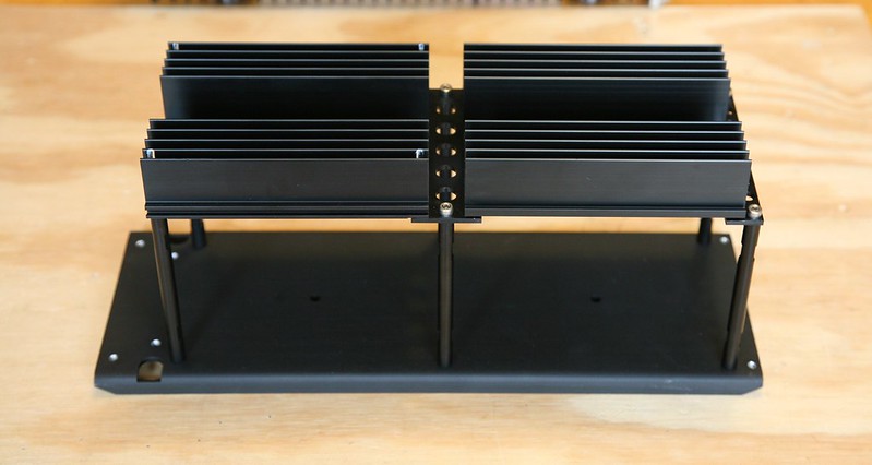
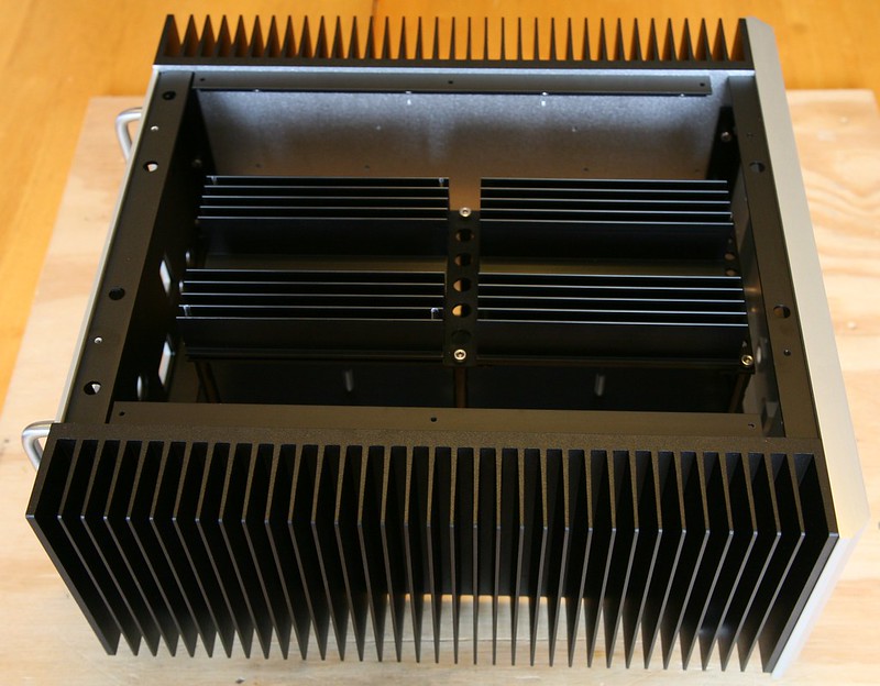
Case Assembly - Transformer Cradle
Unpack cradle plate, vertical standoffs and CRC heatsinks.
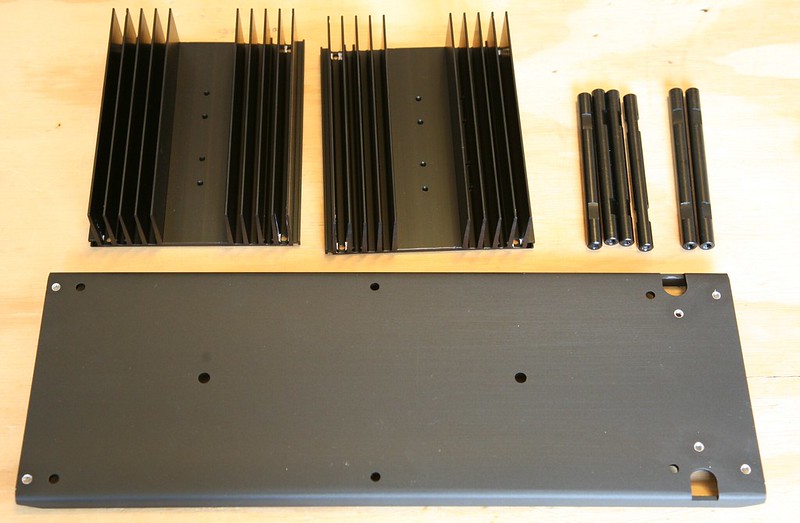
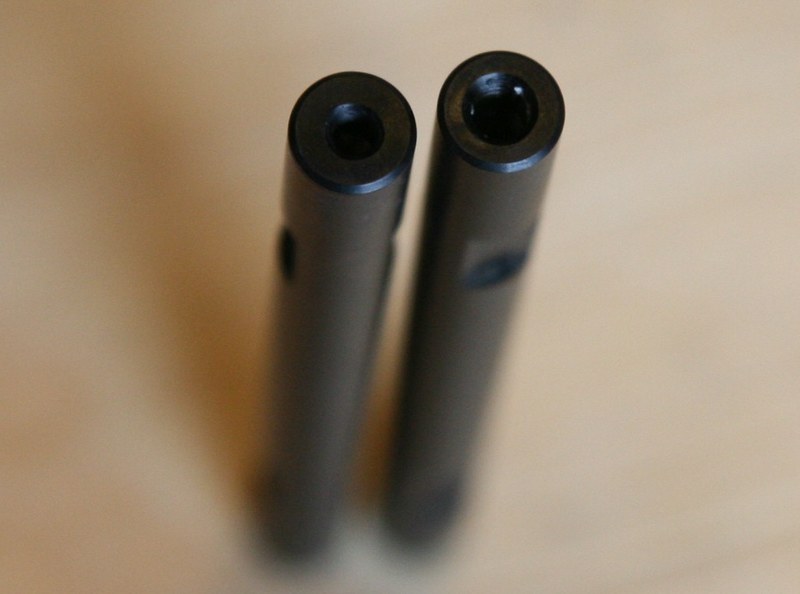
There are 6 standoffs that all appear to be the same initially. Upon closer review, one will notice that two of the standoffs are slightly longer. These two standoffs are M4 threaded on one end, and M3 threaded on the other.
There are (6) non-threaded holes along the sides of the cradle to accept the M4 standoff bolts. Two of the standoff mounting holes are set slightly inward. Place the two longer standoffs at these holes with the M4 threaded end against the cradle plate, and fasten with M4 x 10mm long bolts. Make sure the cradle plate is oriented correctly, with the flat side facing up.
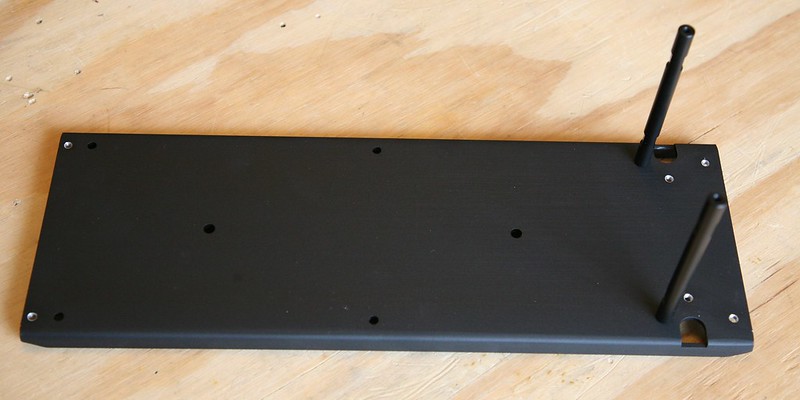
Fasten the remaining standoffs with M4 x 10mm bolts.
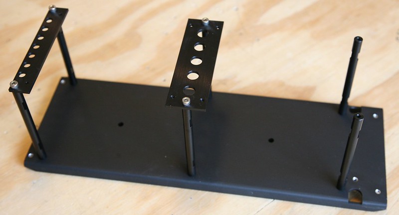
There are two mounting brackets to attach the CRC heatsinks to the standoffs. Fasten the wider bracket to the center pair of standoffs, and the narrower bracket to the outside shorter pair of standoffs with M4 x 10mm bolts.
Mount the transformers with the supplied M5 x 90mm bolts. The bolts are designed to bolt through the transformer mounting cap plate (supplied by SumR), and thread into the supplied black transformer cradle feet.
Mount the CRC heatsinks to the standoffs and standoff mounting brackets with (8) M3 x 10mm bolts.
Unpack cradle plate, vertical standoffs and CRC heatsinks.
There are 6 standoffs that all appear to be the same initially. Upon closer review, one will notice that two of the standoffs are slightly longer. These two standoffs are M4 threaded on one end, and M3 threaded on the other.
There are (6) non-threaded holes along the sides of the cradle to accept the M4 standoff bolts. Two of the standoff mounting holes are set slightly inward. Place the two longer standoffs at these holes with the M4 threaded end against the cradle plate, and fasten with M4 x 10mm long bolts. Make sure the cradle plate is oriented correctly, with the flat side facing up.
Fasten the remaining standoffs with M4 x 10mm bolts.
There are two mounting brackets to attach the CRC heatsinks to the standoffs. Fasten the wider bracket to the center pair of standoffs, and the narrower bracket to the outside shorter pair of standoffs with M4 x 10mm bolts.
Mount the transformers with the supplied M5 x 90mm bolts. The bolts are designed to bolt through the transformer mounting cap plate (supplied by SumR), and thread into the supplied black transformer cradle feet.
Mount the CRC heatsinks to the standoffs and standoff mounting brackets with (8) M3 x 10mm bolts.
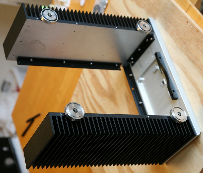
Case Assembly - Main Heatsinks
Unpack 350mm heatsinks, front panel angle brackets, top cover angle brackets, and silver case feet.
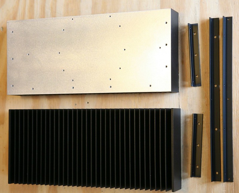
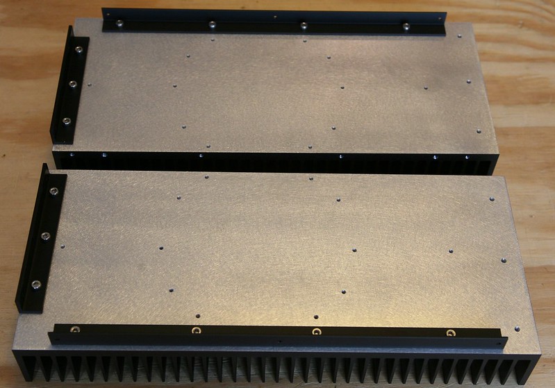
Fasten top cover angle bracket to heatsink with (4) M4 x 6mm bolts. To ensure the top panel will sit flush with the top of the heatsinks, first loosely install all (4) M4 bolts. Once all (4) bolts are in place, push bracket toward the top of the heatsink and tighten the M4 bolts.
Now fasten the front panel angle bracket to the heatsink with (3) M4 x 6mm bolts. To ensure the front panel will sit flush against the heatsinks, loosely install the M4 bolts. Now stand the heatsink on its end on a flat surface, and tighten the M4 bolts. This should ensure the bracket is flush with the edge of the heatsink.
Install the 30mm diameter O-Rings into the silver case feet. A bit of silicone adhesive in the groove of the foot will prevent to O-Rings from falling out.
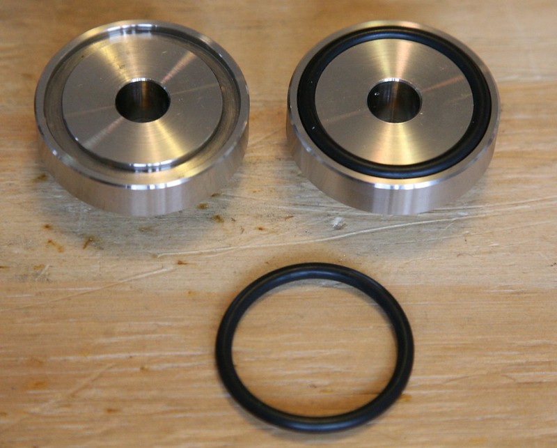
Fasten the case feet to the heatsinks using M4 x 10mm bolts.
Unpack 350mm heatsinks, front panel angle brackets, top cover angle brackets, and silver case feet.
Fasten top cover angle bracket to heatsink with (4) M4 x 6mm bolts. To ensure the top panel will sit flush with the top of the heatsinks, first loosely install all (4) M4 bolts. Once all (4) bolts are in place, push bracket toward the top of the heatsink and tighten the M4 bolts.
Now fasten the front panel angle bracket to the heatsink with (3) M4 x 6mm bolts. To ensure the front panel will sit flush against the heatsinks, loosely install the M4 bolts. Now stand the heatsink on its end on a flat surface, and tighten the M4 bolts. This should ensure the bracket is flush with the edge of the heatsink.
Install the 30mm diameter O-Rings into the silver case feet. A bit of silicone adhesive in the groove of the foot will prevent to O-Rings from falling out.
Fasten the case feet to the heatsinks using M4 x 10mm bolts.
Last edited:
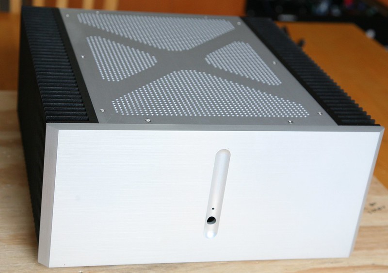
Case Assembly - Front Panel
Unpack the front panel, top panel angle bracket, and bottom transformer cradle bar.
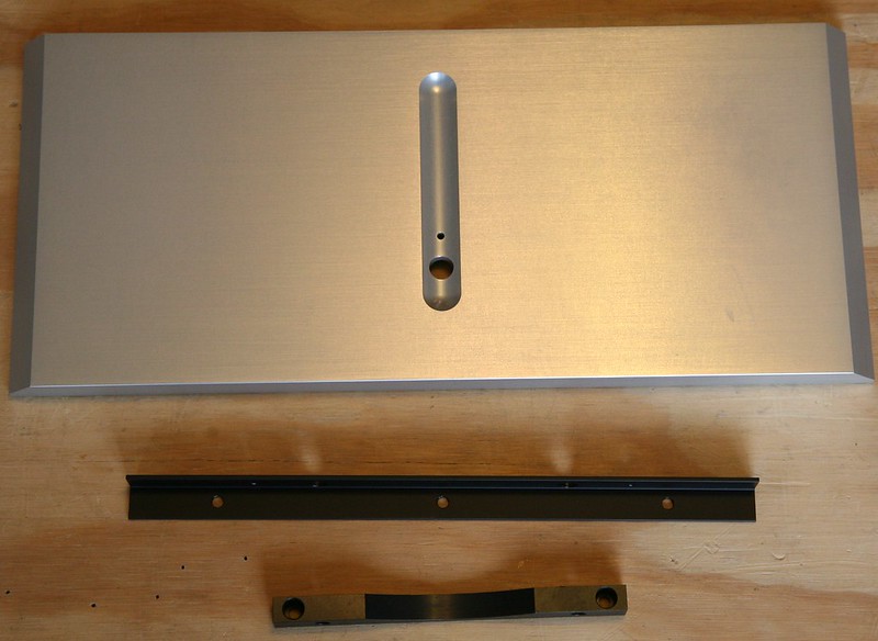
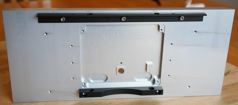
Fasten the top panel angle bracket to the back-side of the front panel with (3) M4 x 10mm bolts. To ensure the top panel will sit flush with the heatsinks, loosely install the M4 bolts. With the M4 bolts in place, push the angle bracket toward to top of the front panel and tighten the bolts.
Mount the transformer cradle bar with (2) M4 x 10mm bolts. Orient the cradle bar with the M4 countersunk holes (for attachment to the cradle itself) facing upward.
Unpack the front panel, top panel angle bracket, and bottom transformer cradle bar.
Fasten the top panel angle bracket to the back-side of the front panel with (3) M4 x 10mm bolts. To ensure the top panel will sit flush with the heatsinks, loosely install the M4 bolts. With the M4 bolts in place, push the angle bracket toward to top of the front panel and tighten the bolts.
Mount the transformer cradle bar with (2) M4 x 10mm bolts. Orient the cradle bar with the M4 countersunk holes (for attachment to the cradle itself) facing upward.
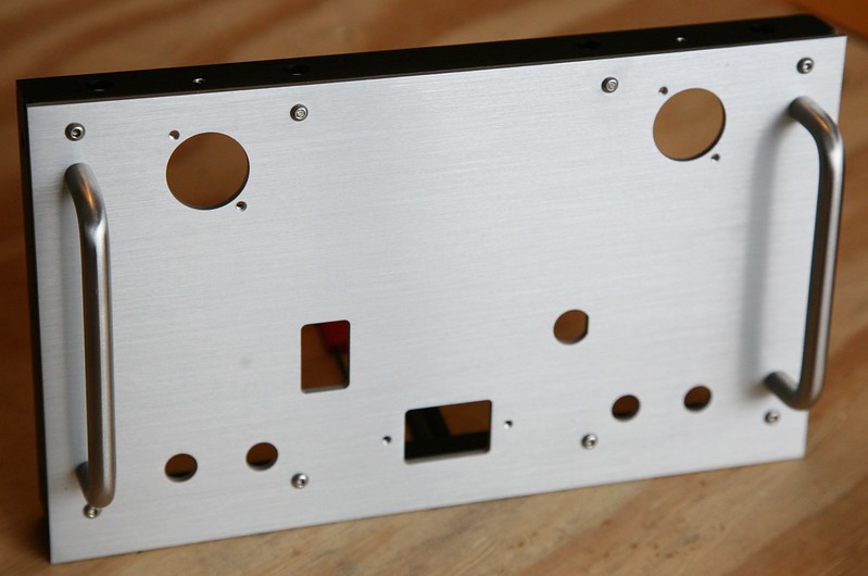
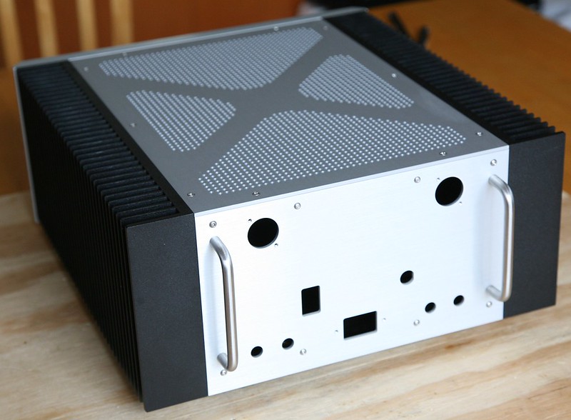
Case Assembly - Rear Panel
Unpack the rear panel, rear bracket and rear panel handles.
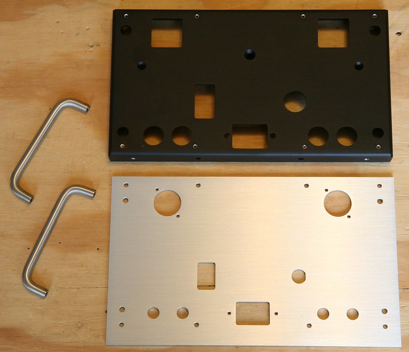
First mount the auxiliary transformer to the rear panel using the M5 x 35mm countersunk bolt. Next mount the rear panel to the rear bracket with (8) M3 x 10mm button head bolts. Lastly, fasten the handles to the rear panel with (2) M4 x 10mm bolts per handle.
Unpack the rear panel, rear bracket and rear panel handles.
First mount the auxiliary transformer to the rear panel using the M5 x 35mm countersunk bolt. Next mount the rear panel to the rear bracket with (8) M3 x 10mm button head bolts. Lastly, fasten the handles to the rear panel with (2) M4 x 10mm bolts per handle.
Case Assembly - Main Case Component Assembly
Lay the front panel flat with front face down, and place the heatsinks on end over the front panel. Loosely fasten the heatsinks to the front panel with (2) M4 x 10mm bolts per bracket. With the bolts loosely in place, push the heatsink toward the top for proper alignment. The top side of the heatsinks should be flush with the top edge of the front panel. Do not tighten bolts yet.
Slide the rear panel assembly between the heatsinks with the XLR input jacks toward the top. Lay the case on its side and fasten the rear panel assembly to the heatsinks with (6) M3 x 6mm bolts. Before tightening the bolts, verify the face of the rear panel is sitting flush with the back of the heatsinks. Tighten rear assembly bolts to heatinks. Verify the alignment of the front panel and tighten the front panel bracket bolts to heatsinks
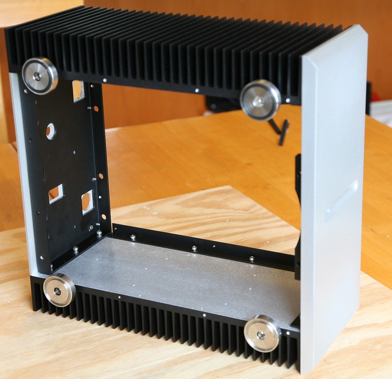
Place the transformer cradle on its feet, and slide the case over the top of the cradle. The two slightly longer transformer cradle standoffs (did not require a mounting bracket) should be located toward the rear of the case.
Loosely fasten the transformer cradle to the case, with (2) M4 x 20mm countersunk screws (front bracket), and (2) M4 x 16mm pan head screws (rear bracket). These screws are intended to be installed loosely so the transformer cradle is not firmly coupled to the rest of the chassis (vibration isolation). Place lock-nuts on underside of case to prevent the screws from coming free.
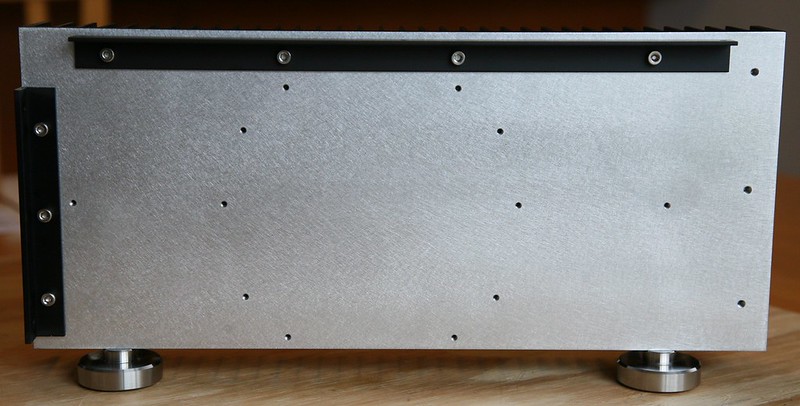
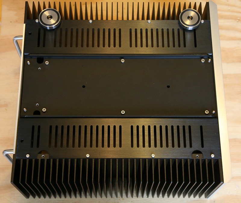
Flip the case over with the bottom facing upwards and remove the silver case feet. Unpack the vented bottom covers and install with (4) M3 x 6mm bolts each. The vented covers should be oriented with the bent edge facing toward the inside of the case. Reinstall silver case feet.
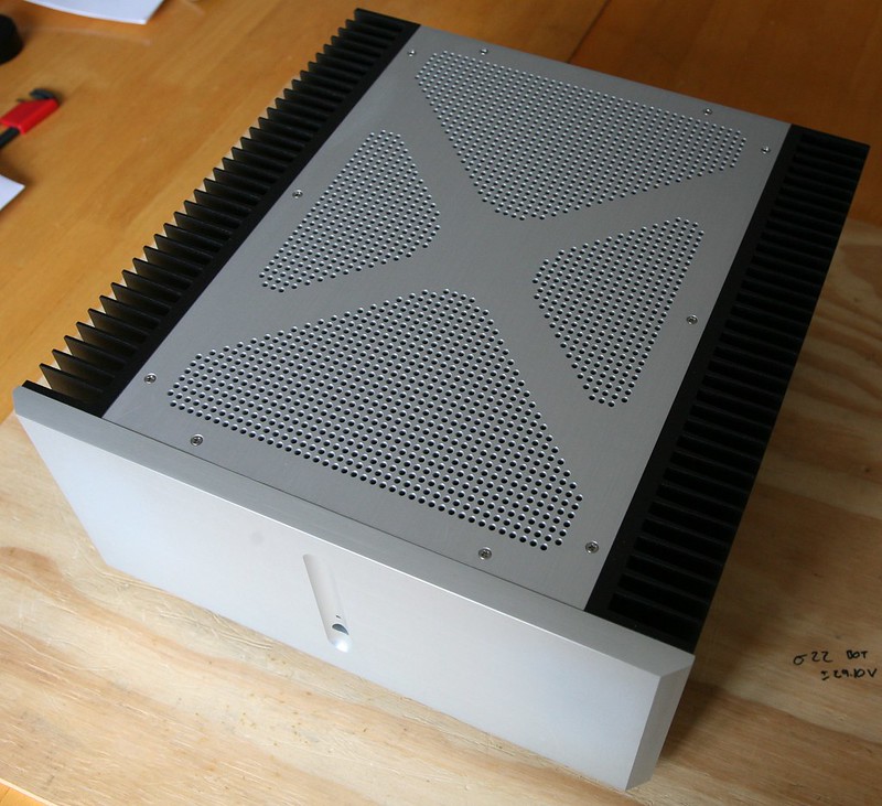
Turn the case over onto its feet, and install the top panel with (10) M3 x 8mm countersunk screws.
Lay the front panel flat with front face down, and place the heatsinks on end over the front panel. Loosely fasten the heatsinks to the front panel with (2) M4 x 10mm bolts per bracket. With the bolts loosely in place, push the heatsink toward the top for proper alignment. The top side of the heatsinks should be flush with the top edge of the front panel. Do not tighten bolts yet.
Slide the rear panel assembly between the heatsinks with the XLR input jacks toward the top. Lay the case on its side and fasten the rear panel assembly to the heatsinks with (6) M3 x 6mm bolts. Before tightening the bolts, verify the face of the rear panel is sitting flush with the back of the heatsinks. Tighten rear assembly bolts to heatinks. Verify the alignment of the front panel and tighten the front panel bracket bolts to heatsinks
Place the transformer cradle on its feet, and slide the case over the top of the cradle. The two slightly longer transformer cradle standoffs (did not require a mounting bracket) should be located toward the rear of the case.
Loosely fasten the transformer cradle to the case, with (2) M4 x 20mm countersunk screws (front bracket), and (2) M4 x 16mm pan head screws (rear bracket). These screws are intended to be installed loosely so the transformer cradle is not firmly coupled to the rest of the chassis (vibration isolation). Place lock-nuts on underside of case to prevent the screws from coming free.
Flip the case over with the bottom facing upwards and remove the silver case feet. Unpack the vented bottom covers and install with (4) M3 x 6mm bolts each. The vented covers should be oriented with the bent edge facing toward the inside of the case. Reinstall silver case feet.
Turn the case over onto its feet, and install the top panel with (10) M3 x 8mm countersunk screws.
That's it for now. As I progress with my build, I try to post some more guidelines/tips for things like board mounting, wiring, etc.
Horio,
How dare you rest the case with the faceplate directly on the bench😱
I would be horrified to scratch it!
Looks fantastic!
Nic
How dare you rest the case with the faceplate directly on the bench😱
I would be horrified to scratch it!
Looks fantastic!
Nic
Thanks, Greg.....
.....for your "assembly manual". It will take a lot of the mystery out of the case assembly. Your calling out the hardware (screws, bolts, etc) will also help prevent me from "screwing up" my case.
Very nicely done. And appreciated......
.....for your "assembly manual". It will take a lot of the mystery out of the case assembly. Your calling out the hardware (screws, bolts, etc) will also help prevent me from "screwing up" my case.
Very nicely done. And appreciated......
Greg,
May be more of an esthetic thing, than anything else. The metric hardware--are you using allen button-head fasteners on your case (except in those instances where the machined plates indicate a need for countersunk fasteners).
Perhaps it will become clear once I get my "bits and pieces" of the case.....
Thanks.......
All of the visible screws (except the small M3 button head screws use to attach the rear panel to the rear bracket), are countersunk. The screws on the bottom of the case are standard metric allen bolts. Patrick and Mark were nice enough to give us a complete hardware kit with the case. Not sure if that answers your question.
Greg, sorry--"senior moment" here. I had forgotten the hardware will come with the case parts. Wow--I'm really looking forward to this one....!!
That's it for now. As I progress with my build, I try to post some more guidelines/tips for things like board mounting, wiring, etc.
Hi,
It is beautiful! The best so far! How much you will have to spend for making a case like yours?
The aluminum is pretty tough. Just make sure your bench surface is clean! 🙂
The Front Panel surface is anodized (aluminum oxide). The hardness of the "coating" is about HRc60 or above. But I'll still put a cloth on the bench first. 😀
The photos are great. Thanks Horio.
Mark
- Status
- Not open for further replies.
- Home
- Amplifiers
- Pass Labs
- F5X Case