Is it just me, or do these big power mosfets have a similar transfer curve at typical amp voltages and currents to the one Nelson likes so much in Zen V8?
Might need some serious drive current though!
http://www.fairchildsemi.com/ds/FD%2FFDA69N25.pdf
Anyone tried one of these in an amplifier? Seems they are very well suited to class A with those ridiculous power ratings.
Might need some serious drive current though!
http://www.fairchildsemi.com/ds/FD%2FFDA69N25.pdf
Anyone tried one of these in an amplifier? Seems they are very well suited to class A with those ridiculous power ratings.
Attachments
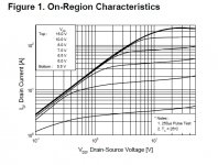
Figure 2 shows why. Because these devices are built with the 'vertical' structure, they have an exponential transfer. As you can see Vgs varies more, and becomes more non-linear as Id approaches 0A. (keep in mind the graph is logarithmic) If you intended on straightening the transfer curve to a more ideal y=x function, you need to create the inverse of the exponential function, a logarithmic function. At higher currents, the change in current is much greater vs the change in Vgs, above the 'knee' of the transfer curve, these devices exhibit fair linearity at class A bias. It is when you use them for class AB that things really get ugly and very high frequency distortion is present, and is related to the transconductance droop at low currents, <200-300mA. For class AB operation, in order to straighten the expo transfer curve you have to get a bit complex in the driving stage. On the positive side, these devices have a ft 5X or more than that of a ring emitter type power BJT. Also they can take lots of abuse, in the form of peak power spikes as would be driving a speaker, and do not mind operating at a higher temperature. SOA is only thermally limited.
On the positive side, these devices have a ft 5X or more than that of a ring emitter type power BJT. Also they can take lots of abuse, in the form of peak power spikes as would be driving a speaker, and do not mind operating at a higher temperature. SOA is only thermally limited.Theses look good and have models available on the website, though they won't be the best for audio purposes:
http://www.fairchildsemi.com/ds/FD/FDA70N20.pdf
http://www.fairchildsemi.com/ds/FD/FDA70N20.pdf
I am a fan of the Q-fet line from Fairchild. The architecture is called Planer Stripe, because instead of cells like in a hexfet the 'cells' are stripes, resulting in lower gate charge vs change in conductance, and as I understand it the fabrication process is simpler and cheaper then hextype devices. Plus I think they are a bit more rugged. I have not used Uni-fets so I can't comment on their performance as an output stage but I think they are similar to planer stripe.
The CISS of that one is huge, but if you are using them in class A it should have much less effect since the change in Vgs will be small. If you look at fig 5, Crss is defined as Cgd. Cgd is what would be more concerning here. Once Vds is lower than 10V, Cgd has more serious effect. I would choose a device with lower Gm that will have a less significant Cgd. Everything in electronics is a compromise of different properties. Unfortunately the perfect ideal transistor has yet to be invented.
- Status
- This old topic is closed. If you want to reopen this topic, contact a moderator using the "Report Post" button.
- Home
- Amplifiers
- Pass Labs
- Triodey transfer curves