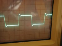
about 20Vp-p. The amp clips with a sine wave at about 22Vp-p so just under clipping. The sq wave still has ringing at lower p-p voltages as well, although at lower voltages it has slightly less ringing. The pic is at 10Vp-p.
Would ferrites somewhere possibly help?
Would ferrites somewhere possibly help?
Attachments
about 20Vp-p. The amp clips with a sine wave at about 22Vp-p so just under clipping. The sq wave still has ringing at lower p-p voltages as well, although at lower voltages it has slightly less ringing. The pic is at 10Vp-p.
Would ferrites somewhere possibly help?
Hi!Which is the maximum undistorted output signal with a sinusoidal input signal?
The output load is 4 ohms or 8 ohms?
Can you post the picture of the oscilloscope?
As I say this because in my first mini aleph powered with +18 V 0-18V I made a mistake, I used the 0.33-ohm resistors instead of 0.47 ohms, the result was a distortion early at about 7w of power output.
I do not know if this information will be useful for you but i hope this.
")
this thread is getting more interesting ... thanks to ZM that is always available to answer our questions.
Do you know what are C102 and C105, why in BrianGT pcb there isn't C105?you have 2 of 1nF there ; C102 and C105
in same places
C104 from 10pf to 15pf ?I imagine it could affect the frequency response!
If yes how to determine the right value?
hmmm...This caps are objects always the most mysterious!
This thread is getting more interesting ... thanks to ZM that is always available to answer our questions.
Thanks.
Last edited:
Hi!Which is the maximum undistorted output signal with a sinusoidal input signal?
22Vp-p
The output load is 4 ohms or 8 ohms?
I'm using an 8R 100W load resistor
As I say this because in my first mini aleph powered with +18 V 0-18V I made a mistake, I used the 0.33-ohm resistors instead of 0.47 ohms, the result was a distortion early at about 7w of power output.
I have .47R source R's and clipping with a sine wave occurs at about 22Vp-p (about 8W or so) I'm assuming that this is reasonable with +/- 13.8V rails.
now desolder both 1nF caps - they;re antioscillation thingie , observe that you don;t have oscillation ,and the fiddle with value of C4
try 15pF for start
OK, thanks. I'll report back shortly.
22Vp-p
I'm using an 8R 100W load resistor
I have .47R source R's and clipping with a sine wave occurs at about 22Vp-p (about 8W or so) I'm assuming that this is reasonable with +/- 13.8V rails.
The Power out with 13,8V is ok! I think too that the cause should be the C4/R15 conbinate values.I think too that you have to try to change (slightly)these values.
Bingo!!
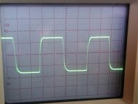
OK, that made a big difference. I paralleled another 10pf with C4 for a total of 20pf.
I'm starting to understand.......R15 is the feedback R and C4 is the compensation cap, correct? Now I want to play with reducing feedback........
So my new square wave would indicate a bit of HF loss, correct? Leading edge is a little rounded. Looks like for 100K feedback R, the optimum C is somewhere between 10 and 20pf. Of course my pf cap selection is a bit thin.....
Thanks ZM!!
Attachments
Hi!ZM what do you think about 15pf value i think it will/schould be perfectthat's good
leave it as is
Hi! BW do you think that you will try with 15pF or not?OK, that made a big difference. I paralleled another 10pf with C4 for a total of 20pf.
I'm starting to understand.......R15 is the feedback R and C4 is the compensation cap, correct? Now I want to play with reducing feedback........
So my new square wave would indicate a bit of HF loss, correct? Leading edge is a little rounded. Looks like for 100K feedback R, the optimum C is somewhere between 10 and 20pf. Of course my pf cap selection is a bit thin.....
Thanks ZM!!
Hi! BW do you think that you will try with 15pF or not?
If I had one I would try it......I'm going to do the other channel and listen for a while.
I'll order a few values on my next Digikey order.
- Status
- This old topic is closed. If you want to reopen this topic, contact a moderator using the "Report Post" button.
- Home
- Amplifiers
- Pass Labs
- Aleph 30 the best choice of C1 C2 C3 on brian gt PCB