F5 v3 Semi-Turbo with Lateral Mosfets...
Hi,
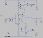
This is my version of an F5 "semi" Turbo with Lateral mosfets. I call it "semi" because of the limitation in current of the Lateral compared to verticals and I want to use only +/-42Vdc.
As a reminder one issue with Lateral in the common source configuration such as the F5 is the low transconductance which limits the output stage gain.
Second issue is the low threshold voltage compared to Laterals which reduces the jfet load resistor thus reduces the gain of the first stage.
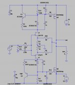
In order to try to solve both issues, we can use 4 Lateral mosfet to have a similar output stage gain as a single vertical. Also, we can use an intermediate mosfet stage which serves 2 purposes:
1) increase the Load resistor of the Jfet input stage thus increase gain (vertical mosfet has a high threshold voltage)
2) Allow to use a higher drive current for the mosfet outputs and avoid using jfet in parallel
Since the GSD pin out of Lateral compared to GDS of vertical mosfets, there is limited PCB available in common source configuration output stage.
My goal is to use a standard F5 PCB available from multiple vendors and then:
1) use a custom daughter board to mount the cascode input stage (b/c 42V)
2) build a simple point-to-point output stage using Double-die Lateral to limit the number of connections.
Since I have already the power supply +/-42vdc and the heatsinks, it will be a class A-B with about 800ma bias.
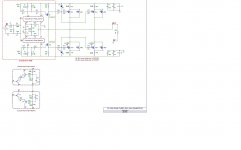
See attached concept. Before I build it I would appreciate comments on the idea and improvements.
Thanks
Fab
Hi,
This is my version of an F5 "semi" Turbo with Lateral mosfets. I call it "semi" because of the limitation in current of the Lateral compared to verticals and I want to use only +/-42Vdc.
As a reminder one issue with Lateral in the common source configuration such as the F5 is the low transconductance which limits the output stage gain.
Second issue is the low threshold voltage compared to Laterals which reduces the jfet load resistor thus reduces the gain of the first stage.
In order to try to solve both issues, we can use 4 Lateral mosfet to have a similar output stage gain as a single vertical. Also, we can use an intermediate mosfet stage which serves 2 purposes:
1) increase the Load resistor of the Jfet input stage thus increase gain (vertical mosfet has a high threshold voltage)
2) Allow to use a higher drive current for the mosfet outputs and avoid using jfet in parallel
Since the GSD pin out of Lateral compared to GDS of vertical mosfets, there is limited PCB available in common source configuration output stage.
My goal is to use a standard F5 PCB available from multiple vendors and then:
1) use a custom daughter board to mount the cascode input stage (b/c 42V)
2) build a simple point-to-point output stage using Double-die Lateral to limit the number of connections.
Since I have already the power supply +/-42vdc and the heatsinks, it will be a class A-B with about 800ma bias.
See attached concept. Before I build it I would appreciate comments on the idea and improvements.
Thanks
Fab
Attachments
Last edited:
What happens if the two cascode halves charge up at different rates?
Will that output a big offset?
Can the two 22uF be replaced with one 10uF and no middle connection?
The extra driver stage will introduce extra phase error. This may require compensation to maintain good stability. The standard F5 already has significant overshoot on fast signals.
Will that output a big offset?
Can the two 22uF be replaced with one 10uF and no middle connection?
The extra driver stage will introduce extra phase error. This may require compensation to maintain good stability. The standard F5 already has significant overshoot on fast signals.
What happens if the two cascode halves charge up at different rates?
Will that output a big offset?
Can the two 22uF be replaced with one 10uF and no middle connection?
Hi AndrewT
That is interesting questions but this cascode is exactly the same as the recent F5 Turbo V3 of Pass. See this link for Nelson comment: http://www.diyaudio.com/forums/pass...tive-my-interest-balanced-f5.html#post2441918
Also: http://www.diyaudio.com/forums/pass...ve-my-interest-balanced-f5-2.html#post2442362
I taught that the charge up would happen mainly at amp power up...
The extra driver stage will introduce extra phase error. This may require compensation to maintain good stability. The standard F5 already has significant overshoot on fast signals.
I have also a standard F5 but I do not remember it had significant overshoot. However I will try to test it to confirm maybe tonight.
For this design with extra driver stage it does not seem to have a significant overshoot according to the simulator with 10n to 1uf in parallel with 8 ohms at Square of 10KHz... However, I can install a small miller cap if really required.
My goal here is to get a similar feedback factor as the standard F5 and improved linearity because of the Lateral mosfets. Hoping that the sound result will worth the effort.: rolleyes:
Thanks
Fab
Last edited:
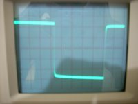
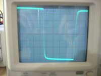
Overshoot of standard F5
See attached, no overshoot at all. The picture is blurry but it is a straight line. I must admit that I have a 68pf cap at input of amp but my generator is relatively fast (3MHz capacity for Square signal).
Thanks
Fab
Take out the capacitor loading and see if any overshoot remains.
See attached, no overshoot at all. The picture is blurry but it is a straight line. I must admit that I have a 68pf cap at input of amp but my generator is relatively fast (3MHz capacity for Square signal).
Thanks
Fab
Attachments
F5 Semi Turbo Stability
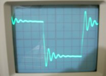
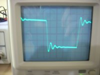
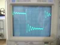
I have assembled one set on my bench. As Andrew pointed earlier, the stability is less easy to obtain than with a standard F5 and we can see the overshoot on only resistive load. I had to add 220pf miller caps and increase the input cap to about 470pf and then I got the attached results.
Notes:
I have not installed the cascode input stage so far. I have tested with about 30Vdc only.
I have only one set of Double die mosfet instead of 2 yet.
The output impedance seems to be high at about 1 ohm...
1st scope: 10kHz, 8 ohms only
2nd scope: 8 ohms and 470nf cap in parallel
3rd trace: 8 ohms and 470nf cap in parallel but with added inductor at amp output
Any comments?
Thanks
Fab
Attachments
Last edited:
Hello FAB
I allso want to build an F5 with the same lateral mosfets and I tried to imagine different sorts of current draw to solve the issue of the low threshold and I came to the following idea (sorry I am not used to post images):
between R1 (4 kOhms?)and jfet insert a zener diode (15 ...20volts)
allso connected between jfet and supply rail: a resistor (+- 2k Ohms depending on bias)
with LTSPICE (beginner and problems with right models...?) it seems to work quite well
I would apreciate any comments
Thanks
Paul
yes I remove allmost everything, keeping:
laterals
R1 preselected for YFs matching (I prefer avoiding adjustable resistor in signal path)
zener 15volts between R1 and jfet
jfet
plus adjustable resistor between rail and jfet (bias adjust) "Rb"
this resistor "Rb", with the help of zener will "steal" current from R1 and adjust bias,
the zener keeping a fairly constant and high voltage across it, (plus Vgs of laterals, unfortunately)
another drawback is less gain but one can have a rather big value for R1, at the cost of bandwith...
the zener replaces the cascode (not so good for PSRR but ok for JFet voltage)
my plans do not have any temperature compensation nor source resistor, simpler than F5! so I need a good zener (stable in temperature) or equivalent LEDs? IR diodes?
your suggestions ale welcomed for stability and sound quality.
project: multiway 4 amp per side, total: 8!
1 "double" lateral
SMPSU: +/-32v 800W x2 from connexelectronic, yes SMPSU! I will be shot for that!!!
bias: 50...500 mA? I hope to find a "magic bias" to have linear gain in the crossover region and identical to the gain in class B region...
(square law rules from Ian Hegglun)
Cheers
Paul
different approach...
OK, I understand now. Thanks for the picture.
This is interesting, you have replace the resistive load by a current source but you use only a portion of the voltage drop (and current too...) through the resistor to bias de Lateral mosfet.... Are you sure you have enough drive current for the mosfet?
Have you evaluated how much more gain in the input stage that it will provide compared to the single resistor to compensate for the lower gain of the Lat mosfet compared to vertical?
What are your reasons to avoid cascode in the input stage?
I suppose that you will still use double die Lateral mosfet (single or double pairs?) to ensure enough overall gain...
Does it sim well?
Thanks
Fab
trying to put an image (!)
added Q1 and Q2
OK, I understand now. Thanks for the picture.
This is interesting, you have replace the resistive load by a current source but you use only a portion of the voltage drop (and current too...) through the resistor to bias de Lateral mosfet.... Are you sure you have enough drive current for the mosfet?
Have you evaluated how much more gain in the input stage that it will provide compared to the single resistor to compensate for the lower gain of the Lat mosfet compared to vertical?
What are your reasons to avoid cascode in the input stage?
I suppose that you will still use double die Lateral mosfet (single or double pairs?) to ensure enough overall gain...
Does it sim well?
Thanks
Fab
Last edited:
It sims well but it's the first time i use LT spice and I had some trouble finding the right components: jfets (IDSS a bit high),1 pair laterals double die (I forced VGS off a bit high: 0.8volts which vith about 200mA bias gives VGS 1 volt IIRC....), maybe they compensate each other...
in the original F5 R1 and pot equates to 1k as well IIRC,
simulating with a single resistor gives a R24 value around 300 ohm
with my system you could use even a bigger value for R24 , I tried 2200Ohm
I think with too big a R24 there is the risk of too high impedance and less bandwith
and a sort of inbalance and stability problem between R24 and the current source.
I tried various solutions of current source keeping the cascode :
but with R24 =2200 (I could try again with 1k)
jfet: seemed hard to tune source resistor around 8.5 ohm very sensible to the value
and Jfet current source below 2 VGs off is not recommended, and they draw less current with rising temperature, witch is the opposite of stability
BJT: could be better, specially with a current mirror, I do not remember why I did not pursue this way, wanting to keep things very simple...
I allso tried a simple resistor between jfet and rail but then the cascode is reverse biased when lateral is off, did not like it....
so this is where I stand, with a good zener 15 v thermal drift should not be a problem, R7 is not too difficult to tune, I loose some of the avantages of the cascode, retaining the voltage drop... 15 volt zener should not be noisy as I read on another thread....
I was stuned by your design: why didn't I think of it!!!!.... but then again temperature compensation, I would like to retain the nice properties of laterals
so far it sims ok with 32v rails /4 ohm (8amp)... and my project beeing multiamplification I could trade bandwith for gain for the bass (below 300 Hz)
medium: B&G neo10 dipole 8 Ohm said to be purely resistive (nice driver!)
tweeter neo3 dipole
Voilà
Paul
...
Fab: your design is probably the best solution, I will have a go at it (spice) with drain resistor to have a fairly constant dissipation. Vgs th: 5 V is very tempting!
did you built it?
cheers
Paul
Hi Paul
See http://www.diyaudio.com/forums/pass-labs/209568-f5-semi-turbo-lateral-mosfets.html#post2968732
But this is the version w/o the cascode. The thermal compensation of the "p-mos" type mosfet can be adjusted with a thermistor as per my schematics (depending of the drain resistor value as you indicate) and do not forget the miller cap (you may add a zero by using an RC instead of the simple C...). This is the drawback of this follower stage compared to the original F5

I have not completed the project and switched to another one since there was not so much interest...at the time...so I have not listened to it. I have built the version of http://www.diyaudio.com/forums/pass-labs/162042-f5-meets-buzquito.html#post2097690 and it sounds better to my taste and other friends too than the original F5 I have built. Thus, this one may be interesting too with lateral mosfet... Anyway, I am glad you find it worthy of having a try out
Fab
Last edited:
dreaming dreaming...
here are more thinking:
R7 and R10 to smooth dissipation in M3 and M4 (values to be determined with CISS rise with lower voltage across M3 and M4) advice welcomed
R14 and R16 with CTN to adjust bias independently of gain
R24 and R4 to choose / balance gain of devices
notice high value of R5: 47k! with C2 forms a low pass and seems to give very good results in LTSPICE on square signal 100kHz with C1 (much less noise on fft analysis and no overshot!)
I took M3 M4 IRF9640 IRF530 available in LTSPICE, I read with interrest f5-meets-buzquito and would like to find the best compromise: not obsolete, VGSoff>2volts, low power TO220?... and probably mount them on a small independant dissipator... R1 and R9 could be 100 ohm or more in a linear region.
as for OLG / NFB ... and linearity I am a newbee I do not know where to go!
and SPICE is not real life, shure we are all aiming for the best, that's the magic of this site!
cheers
Paul
Attachments
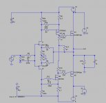
and the winner coul be:
main difference with -f5-meets-buzquito:
R14 R16, ( i like this trick!)
exact resistor values to be detrermined
with 2sk2013 2sj313 if I can get them
psu 32 volts plus 5 volts for drivers
and cascodes for jfets
thanks for your help
comments welcomed
cheers
Paul
main difference with -f5-meets-buzquito:
R14 R16, ( i like this trick!)
exact resistor values to be detrermined
with 2sk2013 2sj313 if I can get them
psu 32 volts plus 5 volts for drivers
and cascodes for jfets
thanks for your help
comments welcomed
cheers
Paul
Attachments
- Status
- This old topic is closed. If you want to reopen this topic, contact a moderator using the "Report Post" button.
- Home
- Amplifiers
- Pass Labs
- F5 Semi-Turbo with Lateral Mosfets...