I decided to take a try at making my own Mini-A layout. I decided to use equivilant surface mount parts for all except for the output resistors and output devices. It is pretty much Grey's original schematic, with a couple of additions suggested in the thread.
Here is the schematic.
I should be getting a pair of boards made in a couple of weeks for testing.
As for the parts, the caps will be panasonic PPS film, and Panasonic FK electrolytics (lower impedence version of the FC).
I started a small stereo chassis for these things today as well")
--
Brian
Here is the schematic.
I should be getting a pair of boards made in a couple of weeks for testing.
As for the parts, the caps will be panasonic PPS film, and Panasonic FK electrolytics (lower impedence version of the FC).
I started a small stereo chassis for these things today as well
--
Brian
Attachments
Brian,
Have you worked with those SMD resistors before? Are they a
pain to solder? I've seen them in commercial amps - that picture
of that Rowland amp based on the GC chips comes to mind. I
guess they "sound" as good as normal 1/4 watt resistors? I just
haven't read much about them on the Forum.
Good luck and keep us posted - sounds like you have the makings
of a really neat little amp here
m.
moe29 said:Brian,
Have you worked with those SMD resistors before? Are they a
pain to solder? I've seen them in commercial amps - that picture
of that Rowland amp based on the GC chips comes to mind. I
guess they "sound" as good as normal 1/4 watt resistors? I just
haven't read much about them on the Forum.
Good luck and keep us posted - sounds like you have the makings
of a really neat little amp here
m.
I actually spend a good amount of time last week, soldering various surface mount stuff. These components are some of the larger surface mount parts that you will see out there. I soldered stuff less then half the size of these.
Parts needed to solder them fairly easily:
-fine tip for the soldering iron
-fine solder (thick stuff will cause you to use too much)
-flux (i like the can of flux paste)
-patience
Basically, I like to put a lot of flux on the board first, and also cleaning the soldiering iron tip in flux.
I then put a bit of solder on one of the pads. With tweezers, I hold the part over the pad, and heat it and place the part, tacking one side down. I then pick the solder back up, and solder the other pad, and touch up the first side.
The flux should wash off really well with normal isopropyl alcohol. I would stay away from defluxer, as it requires a lot of ventilation, and will make you light headed/kill you if you breate it too much.
One consideration is for soldering the film caps: be careful not to heat them up too much. A temperature controlled iron at a lower temperature is a plus. I heated one up just to watch it die.
As for a fun exercise, grab a ruler, and zoom the picture with an image editing program until the size is exactly 2" tall (there are grid lines signifying inches), and this will be the exact size of the board.
I should have boards in a couple of weeks, and if they work out well, and people are interested, I might organize a group order, or provide the layout files to someone who would want to (not-for-profit).
As for the sound of this amplifier, you really can't know til you try it out. On one hand, it might be better with the shorter signal paths, and lower esr caps, but there is a much more limited component selection for this amp... but I figure if Nelson is using standard digikey-like components (panasonic and other run of the mill) for his commercial amps, then standard digikey components would work just fine for me for this exercise.
Also, there are some exotic SMD parts out there if you search (tantulum resistors, oscon capacitors, etc), but no black gates to my knowledge.
--
Brian
Something I threw together.
It only needs 1 iron, & it makes for clean flat assembly, even for ICs.
I posted it in the 'electronic parts' forum.
http://www.diyaudio.com/forums/showthread.php?s=&threadid=20947
____________
Brian Guralnick.
It only needs 1 iron, & it makes for clean flat assembly, even for ICs.
I posted it in the 'electronic parts' forum.
http://www.diyaudio.com/forums/showthread.php?s=&threadid=20947
____________
Brian Guralnick.
BrianGT said:Here is a strange 3d view that the software gave me... I didn't choose what the components should look like
--
Brian
Hi Brian,
What software are you using???
JF
0805 and bigger, SOT-23 and bigger are no problems to solder. I use also two soldering irons, for the 0805 parts, real easy but it's also easy with only one iron.
IC's with pin spacing 25 mil or less IS not easy to solder!
Brian, nice work! What do the audiophiles say about SMD? I think it's cool.
IC's with pin spacing 25 mil or less IS not easy to solder!
Brian, nice work! What do the audiophiles say about SMD? I think it's cool.
If you are trying to make this as small as possible, you could save a LOT of space by replacing Q1 and Q3 with 2sj109 and mounting Q2 vertically. Mounting R18-21 vertically will save space and probably reduce thermal noise by allowing the resistors to reject heat more efficiently.
Many parts are more compact in their through-hole body than in an SMD. A vertical TO-220 transistor will take up less room than a horizontally surface-mounted one, and Zetex's E-Line package uses less board space than most SMD transistor packages. Electrolytic caps are also more compact in through-hole packages.
Of course, if compactness is not your goal, you should kindly ignore me.
jwb said:If you are trying to make this as small as possible, you could save a LOT of space by replacing Q1 and Q3 with 2sj109 and mounting Q2 vertically. Mounting R18-21 vertically will save space and probably reduce thermal noise by allowing the resistors to reject heat more efficiently.
Many parts are more compact in their through-hole body than in an SMD. A vertical TO-220 transistor will take up less room than a horizontally surface-mounted one, and Zetex's E-Line package uses less board space than most SMD transistor packages. Electrolytic caps are also more compact in through-hole packages.
Of course, if compactness is not your goal, you should kindly ignore me.
Actually, the idea behind this board was to make it small, and use SMD parts. I don't like the idea of putting resistors vertically, because it puts a lot more strain on the pcb contacts. I have a similar opinion about putting the input fets vertically. I also like the idea of the board being lower profile, as it will allow for a smaller chassis.
As for the capacitors, the new Panasonic FK capacitors are lower impedence and smaller then the through hole FC ones.
--
Brian
peranders said:IC's with pin spacing 25 mil or less IS not easy to solder!
Brian, nice work! What do the audiophiles say about SMD? I think it's cool.
I've done it. Just need a paint stripper & soldier paste in an injection tube.
(Done this way if you don't have a soldier paste stencil. With stenciled paste, just place the IC down and do step #5.)
1. Remove existing SMD plating / or paste with soldier wick.
2. flux off.
3. place down IC.
4. make a fine line of paste on top of the IC pins.
5. heat with paint stripper heatgun.
And voila! The paste will magicly separate around the pins before your eyes and the IC will be soldiered down.
Brian, I can solder 25 mils (or even 0.6 mm) IC's but this is not for everyone. You must see good enough and don't tremble too much and your coordination must be good. If I for example have braked hard with my bicycle I get too trembly. You must be well-rested if you shall succeed.
For soldering the small ICs, the school here has a Hakko 852 station, with different tips for different packages. First you need to put solder on the pads, then ou use the tool, pick up the part with suction, then you position the board under the tool, and lower the tool to get the part in place and hit the start button. It blows hot air all over it, then cools it to get a perfect solder.
It worked great for those small SSOP28 parts, such as the latest dacs.
--
Brian
It worked great for those small SSOP28 parts, such as the latest dacs.
--
Brian
Attachments
peranders said:Brian, I can solder 25 mils (or even 0.6 mm) IC's but this is not for everyone. You must see good enough and don't tremble too much and your coordination must be good. If I for example have braked hard with my bicycle I get too trembly. You must be well-rested if you shall succeed.
Using my cheap method, just use a tiny square of double sided schotch tape under the IC. Since the pads are flat from the removal of eisting solder, once the IC is aligned you can actually solder it on with the heat gud during an earthquake. Note, the take may stink a little. Thats why I say, 'use a little square'. Also, the double sided tape is the flatest stuff I could find, & it doesn't allow for IC moval like some other thicker tapes.
1. Remove existing SMD plating / or paste with soldier wick.
2. flux off.
3. place down IC. (with the double sided tape under it.)
4. make a fine line of paste on top of the IC pins.
5. heat with paint stripper heatgun.
BrianGT said:For soldering the small ICs, the school here has a Hakko 852 station, with different tips for different packages. First you need to put solder on the pads, then ou use the tool, pick up the part with suction, then you position the board under the tool, and lower the tool to get the part in place and hit the start button. It blows hot air all over it, then cools it to get a perfect solder.
It worked great for those small SSOP28 parts, such as the latest dacs.
--
Brian
Yes, with the right tools, this is the correct & professional way to do it.
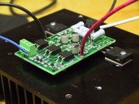
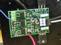
Here is an overhead shot of the layout. It wasn't that hard to solder. I did have a mistake when I was testing it..... I hooked only the positive 15v up to the amplifier, and cranked up the voltage. It managed to kill the BJT in the CCS, but with a simple replacement, the amplifier was up and running on a bench supply, drawing 1A of current off of a dual 15v supply setup.
--
Brian
--
Brian
Attachments
- Status
- This old topic is closed. If you want to reopen this topic, contact a moderator using the "Report Post" button.
- Home
- Amplifiers
- Pass Labs
- yet another Mini-A layout... (with SMD parts)