One of the things that we have been working on in the last two years.
http://www.diyaudio.com/forums/multi-way/62555-milestones-speaker-project.html#post3550578
Only for us, will NOT be a public project.
But we have published almost all details so you can also DIY.")
Patrick
http://www.diyaudio.com/forums/multi-way/62555-milestones-speaker-project.html#post3550578
Only for us, will NOT be a public project.
But we have published almost all details so you can also DIY.
Patrick
Attachments
anyone here that got this amp running for more than 2 hrs but with 2 A bias
how hot Is heatsink
This sunday I'll try 2A with forced ventilation. with 1,5A is hotter than the frying pan (in the Spain summer, maybe in Iceland will works
) , but is stable and sounds so goodOne of the things that we have been working on in the last two years.
http://www.diyaudio.com/forums/multi-way/62555-milestones-speaker-project.html#post3550578
Only for us, will NOT be a public project.
But we have published almost all details so you can also DIY.
Patrick
How much sensitivity?
Regards
Enviado desde mi iPad con Tapatalk HD
See measurements in the article re speaker sensitivity.
I strongly suggest you try 2A with a slow blowing fan.
And buy a multimeter that comes with thermocouple.
They do not cost that much. Twenty something Euros.
Digital Multimeter 20 Function with Thermocouple
Patrick
I strongly suggest you try 2A with a slow blowing fan.
And buy a multimeter that comes with thermocouple.
They do not cost that much. Twenty something Euros.
Digital Multimeter 20 Function with Thermocouple
Patrick
This sunday I'll try 2A with forced ventilation. with 1,5A is hotter than the frying pan (in the Spain summer, maybe in Iceland will works
first you got to measure temperature at your devices case with current bias 1.5 A
how much Is your ambient temperature
first you got to measure temperature at your devices case with current bias 1.5 A
how much Is your ambient temperature
30ºC, in an air conditioned room (42ºC on the street).
I'll try to get a multimeter with temperature.
30°C should be OK with 1.5A.
But your air conditioner has to work over-time to get rid og the heat sink dissipation.
At such ambient temperatures, it is probably better to run Class A/B.
Or if water is not costly then use running tap water to do water cooling.
Patrick
My regular F5 works at 40ºC ambient temperature without flawless on a hifi2000 4U pesante disipante modushop.biz, also my Aleph 3 (Pass Labs made).
Here in the winter the temperature drops to -10ºC
 , probably I won't have temperature problems.
A regular F5 has half the dissipation. The Hifi 2000 has a larger sink.
Maybe you should have used another case with large sinks and make monoblocks.
We had to use a commercially available sink, and Conrad was the largest that was easy to get.
And it was certainly not designed for 40°C ambient.
But you knew that already.
Patrick
Maybe you should have used another case with large sinks and make monoblocks.
We had to use a commercially available sink, and Conrad was the largest that was easy to get.
And it was certainly not designed for 40°C ambient.
But you knew that already.
Patrick
We had to use a commercially available sink, and Conrad was the largest that was easy to get.
And it was certainly not designed for 40°C ambient.
But you knew that already.
Patrick
for what ambient temperature Is designed
for what ambient temperature Is designed
22ºC
http://www.diyaudio.com/forums/pass-labs/208880-f5x-euvl-approach-build-thread-63.html#post3540191
Last edited:
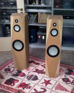
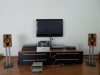
F5X proto II, first living room test
After building a first F5 proto (lab power supply, 1 amplifier board, 2 x single ended configuration) in winter 2011/2012 and subsequent listening we where enthousisatic enough to sign up for the F5X batch 2 GB. However, we dediceded not to go straight for the final version with everything nicely intergrated in the housing, but taking an intermediate step by building a second proto as breadboard version.
Patrick was kindly supporting our plan by making some sample boards of the batch 2 GB available to us upfront for testing.
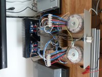
So we build 2 x fully decoupled mono blocks, balanced output, floating X, with the same supply and power amp boards and devices that will later go into the cases. Since we were not patient enough to wait any further with the listening tests the protection board was not intergrated yet. But this has to follow next.
Last monday all pre-tests where completed and we moved the amp to the living room for a first listening test (two people were needed for lifting )
Source: Linn Sneaky, single ended output,
Transducers: B&W CDM1 SE
Well what should I say? Unbelievable!
Pure music, an enourmous level of detail that I have never recognized before, rigid sound stage, in no case any sign of uncertainty.
Although we did not do an one by one comparison with proto 1 we all agreed that proto 2 has substantially improved w.r.t. proto 1.
So fully separated supplies (instead of one common one) and balanced amplifier operation (instead of single ended) makes a clear difference.
Well that´s obvious most of the DIYers would say. Frankly, I did not dare to hope for such a clear difference. But now we have evidence that investiments in component cost and power dissipation pays back.
This is more than enough motivation to keep the speed up even during summer time.
Markus & The Ulm 5FX Build Team
After building a first F5 proto (lab power supply, 1 amplifier board, 2 x single ended configuration) in winter 2011/2012 and subsequent listening we where enthousisatic enough to sign up for the F5X batch 2 GB. However, we dediceded not to go straight for the final version with everything nicely intergrated in the housing, but taking an intermediate step by building a second proto as breadboard version.
Patrick was kindly supporting our plan by making some sample boards of the batch 2 GB available to us upfront for testing.
So we build 2 x fully decoupled mono blocks, balanced output, floating X, with the same supply and power amp boards and devices that will later go into the cases. Since we were not patient enough to wait any further with the listening tests the protection board was not intergrated yet. But this has to follow next.
Last monday all pre-tests where completed and we moved the amp to the living room for a first listening test (two people were needed for lifting )
Source: Linn Sneaky, single ended output,
Transducers: B&W CDM1 SE
Well what should I say? Unbelievable!
Pure music, an enourmous level of detail that I have never recognized before, rigid sound stage, in no case any sign of uncertainty.
Although we did not do an one by one comparison with proto 1 we all agreed that proto 2 has substantially improved w.r.t. proto 1.
So fully separated supplies (instead of one common one) and balanced amplifier operation (instead of single ended) makes a clear difference.
Well that´s obvious most of the DIYers would say. Frankly, I did not dare to hope for such a clear difference. But now we have evidence that investiments in component cost and power dissipation pays back.
This is more than enough motivation to keep the speed up even during summer time.
Markus & The Ulm 5FX Build Team
Attachments
Well phase spitter is very generic term for a device that generates a signal with a shifted phase w.r.t. to input signal. In our case we need 180deg or "just" the same signal with the opposite the sign.
In audio often one transistor with equal emitter and collector resistors and output DC decouling caps are employed for this purpose.
And I tend to agree not regarding this as not a proper balanced source.
Employing a line level audio transformer for generating a balanced voltage signal source for the amps out of the balanced voltage output of the DAC seems to be very simplistic and straight forward me. And it´s symmeric by principle. Of corse the quality of the transforms is key here, but there are nice options around.
I cannot get this approach out of my head, but I need to further elaborate on this.
As an intermediate step. Why not using a simple voltage devider as phase splitter?
Signal
+------------------------> +
|
10k
|
+----------> Amp GND
|
10k
|
+-------------------------> -
Sign Gnd
Well, now the amp GND is swinging but this should not be a problem since the Amp GND is galvanically decoupled from PE.
Stray capacities (tranformers, etc. ) will cause an a-symmetry though.
But is this this worse than the transistor with the decoupling caps?
Since I never saw this simple idea employed as a phase splitter I was griding what might be wrong with my thinking. But so far I could not find something wrong with it besides loosing 6dB of gain compared to the convetional phase splitters.
Remarks and hints are appreciated.
And, I guess next oppertunity I will give it a try.
The mission of our proto 2 is experimenting
Markus
Dave (fitzfish) proposed something similar in his D1 IV for ES9018.
Too fiddly for me.
For safety reasons at least, you want some connection (cap // 2 diodes // power resistor) between your "floating" power amp Gnd and mains earth.
And yes stray capacitance is an issue.
If you intend to float the power amp completely then you might as well do circlotron.
Transformer is still the simplest solution in your case.
This will be the first I would try.
Patrick
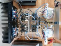
Power supply wiring questions
I was wondering if anyone has photos of how they have wired their power supply in their completed amplifier?
I am mostly wondering about wire runs from the back panel to the two power transformers, and from the regulators to the cap banks.
I certainly have an idea how I will do my amps, but always like to check to see how everyone else has theirs done.
Getting close to testing my CRC power supply and also the circuit boards. First attempt at testing the protection board shows that I need to recheck for a solder bridge or two....even with magnification, SMD soldering still is always challenging...
- Home
- Amplifiers
- Pass Labs
- F5X -- the EUVL Approach - The Build Thread