Alexis's worked OK, so we are building a new board from scratch to cross check.
So put your trust in my poor soldering skills
")
As Alexis's worked OK, my soldering skills are so poor that I have even changed the PCB layout
Really not that difficult. Thin low melting point (lead containing) solder. Flux the board before each component. Thin iron tip. Magnifying glass.
Gain courage with the resistors and caps - then do the chips. For what my advice is worth.
I did also consider a smd rework station, but for that to be better I guess a lot of practice is also needed. I did get a syringe of solder paste, but I can't get it out of there I guess the pro's have some kind of pump
) solder. Flux the board before each component. Thin iron tip. Magnifying glass.Gain courage with the resistors and caps - then do the chips. For what my advice is worth.
I did also consider a smd rework station, but for that to be better I guess a lot of practice is also needed. I did get a syringe of solder paste, but I can't get it out of there
I guess the pro's have some kind of pump> So put your trust in my poor soldering skills
> As Alexis's worked OK, my soldering skills are so poor that I have even changed the PCB layout
Your words against his. I don't take sides.
And such comments are not particularly productive either, if I may say so.
We shall build one ourselves and find out.
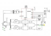
The schematics is correct; 2 people have checked it independently by hand calculation and Spice simulations.
So not design error.
Patrick
> As Alexis's worked OK, my soldering skills are so poor that I have even changed the PCB layout
Your words against his. I don't take sides.
And such comments are not particularly productive either, if I may say so.
We shall build one ourselves and find out.
The schematics is correct; 2 people have checked it independently by hand calculation and Spice simulations.
So not design error.
Patrick
I guess the pro's have some kind of pump
BGA Reballing Station 40 Stencils 80mm 4 Bottles Solder Balls 100g Paste | eBay
something like this maybe??
Congrats Nick!
Regarding the protection board, were there any changes you made or was it simply adjusting some of the jumpers?
The jumpers is really a non-issue. You are best served by placing all of them in the ON position (towards the center of the board) to start with.
75% of the jumpers permit you to do things you would never want to do. I don't know why - but the option is there
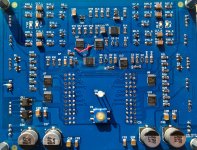
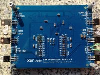
Here are a few photos.
To check the correct operation of the board I use LEDs with current limiting R in series. This gives a nice visual readout of relay behavior.
If all the jumpers are in the ON position you will find that all LEDs are ON in the SBY state and OFF in the ON state.
This assures maximum exposure of DC offset to your speakers and no music when the amp is on
Attachments
Hi Nic,
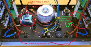
I see a couple of relay at the speaker terminal and are not in the BOM.
1) Was there a group buy for these?
2) What are the specs?
3) Also the relay at the fuse holder, why do you need this?
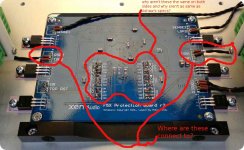
4) On the control board, where are the ISR 1 & 2 connect to?
5) Why are the "On" and "Off" positions different on both sides?
On the mute image you posted earlier, I can also see 2 wires going out from the mute board.
6) To where are these connect to?
Thanks.
I see a couple of relay at the speaker terminal and are not in the BOM.
1) Was there a group buy for these?
2) What are the specs?
3) Also the relay at the fuse holder, why do you need this?
4) On the control board, where are the ISR 1 & 2 connect to?
5) Why are the "On" and "Off" positions different on both sides?
On the mute image you posted earlier, I can also see 2 wires going out from the mute board.
6) To where are these connect to?
Thanks.
Attachments
>1) Was there a group buy for these?
Not that I know of. Heinz1 was kind enough to buy for a few of us in europe.
>2) What are the specs?
I don't recall. Search the threads and you will find it.
>3) Also the relay at the fuse holder, why do you need this?
This is the main relay. It connects fuse to main transformers when on (see the schematics that Patrick posted in the main thread). I use the LSR1 driver on the control board to control this. I think Mark mounted this relay on the transformer cradle. If you want to be able to turn on the amp using the push button on the front panel you need this relay.
>4) On the control board, where are the ISR 1 & 2 connect to?
The mute boards.
>5) Why are the "On" and "Off" positions different on both sides?
All jumpers (except one) are in the same position on both sides.
>On the mute image you posted earlier, I can also see 2 wires going out from the mute board. 6) To where are these connect to?
ISR drivers on control board.
The following is just my own personal observations and thoughts about the protection board functionality. As usual, I may be entirely wrong.
Purpose:
The protection board serves two purposes: firstly it does as its name say protect the speakers in the case of a failure (DC on outputs) and secondly it organizes a proper turn-on sequence of the amp by controlling a series of relays that have been implemented in the F5X build. I have not made the protection part work yet so I will only describe what I have found with the turn-on sequence functionality.
Interface:
The interface between you and the protection circuit is a pushbutton on the front panel of the amp. The state of the amp, determined by the protection board, is reported on the by a bi-color LED. When the amp is OFF the LED is off, when the amp is in standby (SBY) it is red and when ON blue. Pushing the button makes the amp shift between the three states (OFF -> SBY -> ON) in a cyclic manner.
A bug in the layout of the version r3 boards (those that I have) causes a wrong startup sequence where the ON state precedes the SBY state (i.e OFF -> ON -> SBY). According to ashaw this mistake "does not affect functionality", but may be "annoying to some people".
I guess I among those people. I don't like my car to automatically let go of the brake, insert the gear and push the speeder - when I turn the ignition key.......
I will leave it to the designers and engineers to describe and support the fix for the "small layout bug". If you find the bug annoying.
Protection board behavior:
Once the protection board transformer is powered (i.e. when the amp is turned on using the main switch on the back) there is a long delay (about one minute) before anything happens.There is plenty of time to walk out of the house if you are scared that the amp might blow up
After this start up delay (SUD) the master relay (MR) driver goes high and this powers the main transformers. This state of the amp is called "OFF", and the amp protection board status LED will be off. The behavior of the MR driver is hardwired and there are no jumpers to modify it. Once the MR is on it stays on until the main switch is turned of. The main transformer is therefore always powered.
If you have build the F5X and use CRC regulators you will not want to use the MR relay driver to control the master relay as the amp would effectively be on always. An easy workaround for people with CRC regulators is to use one of the speaker relay drivers to operate the master relay (I have taken this road).
Pushing the button shifts the amp state from OFF to SBY and the status LED will turn red. If the button is pushed again the amp moves from SBY to ON and the status LED turns blue. Pushing again brings the amp back to the OFF state. With the start up sequence fix in place the status LED needs to be turned around.
Relay drivers:
The protection board controls 6 relay drivers in addition to the MR driver. These are named LSP1/2 (loud speaker relay), RSR1/2 (regulator relay) and ISR1/2 (input relay) and their intended use is easily understood. The RSR (and MR) drivers are high current 24V drivers intended for power relays. The RSR and ISR drivers are low power 12V drivers intended for signal relays.
The availability of 6 relays allows the user to control left and right channel of the amp independently. I find it difficult to imagine when one would ever want to operate the two channels differently, but the feature is there
It is also possible to use only some of the 6 drivers and connect relays in parallel. To my understanding the drivers deliver sufficient power to support also this configuration.
Jumper control:
The behavior of the relay drivers can be (partially) controlled using the jumpers on the board, the position of which determines in which amp state(s) the 6 relay drivers are high or low.
For each of the 6 relay drivers there are 4 jumpers labeled CB1, CB2, SUD and TRP. These jumpers represents 4 of the 5 states that the amp will ever be in.
CB1 = OFF state
CB2 = standby state (SBY)
SUD = start up delay state
TRP = fault state (i.e. DC on outputs to my understanding)
There is an important last state that the amp may happen to be in (hopefully most of the time), but there are no jumpers to control what happens in this state. This state is ON and all six relay drivers are high.
The jumpers may be put in one of two positions labeled "ON" and "OFF" on the PCB. For my personal testing and experiments I put all the jumpers in the ON position. This is a good and recommended (by me at least) starting point. What happen in this configuration is that none of the 6 relays turn on until the amp is in the ON state. If you want a given relay to come on already in the standby state (for example the main relay) you move the SBY (labeled CB2) jumper from the ON to the OFF position. Logical right
In fact, with the F5X you probably only ever want to move the SBY (CB2) jumpers. Leave the rest in the "ON" position.
The remaining jumpers (OFF=CB1, SUD and TRP) are used to turn the relays high in amp states where this seems either useless or dangerous. For example you may connect the speaker outputs in the fault state if that is to your taste
Purpose:
The protection board serves two purposes: firstly it does as its name say protect the speakers in the case of a failure (DC on outputs) and secondly it organizes a proper turn-on sequence of the amp by controlling a series of relays that have been implemented in the F5X build. I have not made the protection part work yet so I will only describe what I have found with the turn-on sequence functionality.
Interface:
The interface between you and the protection circuit is a pushbutton on the front panel of the amp. The state of the amp, determined by the protection board, is reported on the by a bi-color LED. When the amp is OFF the LED is off, when the amp is in standby (SBY) it is red and when ON blue. Pushing the button makes the amp shift between the three states (OFF -> SBY -> ON) in a cyclic manner.
A bug in the layout of the version r3 boards (those that I have) causes a wrong startup sequence where the ON state precedes the SBY state (i.e OFF -> ON -> SBY). According to ashaw this mistake "does not affect functionality", but may be "annoying to some people".
I guess I among those people. I don't like my car to automatically let go of the brake, insert the gear and push the speeder - when I turn the ignition key.......
I will leave it to the designers and engineers to describe and support the fix for the "small layout bug". If you find the bug annoying.
Protection board behavior:
Once the protection board transformer is powered (i.e. when the amp is turned on using the main switch on the back) there is a long delay (about one minute) before anything happens.There is plenty of time to walk out of the house if you are scared that the amp might blow up
After this start up delay (SUD) the master relay (MR) driver goes high and this powers the main transformers. This state of the amp is called "OFF", and the amp protection board status LED will be off. The behavior of the MR driver is hardwired and there are no jumpers to modify it. Once the MR is on it stays on until the main switch is turned of. The main transformer is therefore always powered.
If you have build the F5X and use CRC regulators you will not want to use the MR relay driver to control the master relay as the amp would effectively be on always. An easy workaround for people with CRC regulators is to use one of the speaker relay drivers to operate the master relay (I have taken this road).
Pushing the button shifts the amp state from OFF to SBY and the status LED will turn red. If the button is pushed again the amp moves from SBY to ON and the status LED turns blue. Pushing again brings the amp back to the OFF state. With the start up sequence fix in place the status LED needs to be turned around.
Relay drivers:
The protection board controls 6 relay drivers in addition to the MR driver. These are named LSP1/2 (loud speaker relay), RSR1/2 (regulator relay) and ISR1/2 (input relay) and their intended use is easily understood. The RSR (and MR) drivers are high current 24V drivers intended for power relays. The RSR and ISR drivers are low power 12V drivers intended for signal relays.
The availability of 6 relays allows the user to control left and right channel of the amp independently. I find it difficult to imagine when one would ever want to operate the two channels differently, but the feature is there
It is also possible to use only some of the 6 drivers and connect relays in parallel. To my understanding the drivers deliver sufficient power to support also this configuration.
Jumper control:
The behavior of the relay drivers can be (partially) controlled using the jumpers on the board, the position of which determines in which amp state(s) the 6 relay drivers are high or low.
For each of the 6 relay drivers there are 4 jumpers labeled CB1, CB2, SUD and TRP. These jumpers represents 4 of the 5 states that the amp will ever be in.
CB1 = OFF state
CB2 = standby state (SBY)
SUD = start up delay state
TRP = fault state (i.e. DC on outputs to my understanding)
There is an important last state that the amp may happen to be in (hopefully most of the time
), but there are no jumpers to control what happens in this state. This state is ON and all six relay drivers are high.The jumpers may be put in one of two positions labeled "ON" and "OFF" on the PCB. For my personal testing and experiments I put all the jumpers in the ON position. This is a good and recommended (by me at least
) starting point. What happen in this configuration is that none of the 6 relays turn on until the amp is in the ON state. If you want a given relay to come on already in the standby state (for example the main relay) you move the SBY (labeled CB2) jumper from the ON to the OFF position. Logical rightIn fact, with the F5X you probably only ever want to move the SBY (CB2) jumpers. Leave the rest in the "ON" position.
The remaining jumpers (OFF=CB1, SUD and TRP) are used to turn the relays high in amp states where this seems either useless or dangerous. For example you may connect the speaker outputs in the fault state if that is to your taste
Last edited:
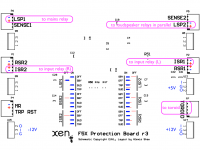
Protection board revisions
The silkscreen shown in the previous post is the one posted by ashaw some pages back. My PCB's are labeled with the same revision number "r3", but the silkscreen is different.
The jumper rows labeled OFF and SBY on the silkscreen posted by ashaw are labeled CB1 and CB2 on my boards.
Do I/we have an old PCB revision?
If not, why was labeling changed from the meaningful OFF and SBY to CB1 and CB2 on the last revision? Curious minds want to understand.......
I can't find photos of the "other side" of the fully tested without issues board published in the main thread here, so I don't know how to check.
Firstly thank you for taking trouble to write the detailed description.
And no, we do not find the wrong sequence acceptable.
At the time we started this project, there was no XEN Audio team, and I had no means to generate Gerber files.
That is the only reason why work has been done by others outside the XEN Team.
Like many others, those persons are doing audio as a hobby, and they do have a normal life to live.
That includes boring things like exams, work, family, health, etc.
So I consider it reasonable to give the person who did the work a chance to rectify any mistakes.
We all make mistakes; I do, so do you.
If there is no further progress to resolve the problem by the end of February, the XEN team will take over the ownership of the protection board.
Should there be any error (be it not ours), we shall then provide 2 solutions :
1) For those who have soldered their protection board, like Nic, a viable work around.
2) For those who have not, all replacement components including new PCBs, passive and active components.
We shall post them then to the local distributors for distribution.
In the future, we shall not release any further projects until we are satisfied that they are all done properly within the team.
There will be no Beta testing outside the team, except for a few selected DIYers
whom we are convinced are experienced enough and do not demand spoon feeding.
All documentations will only be downloadable at our website, so they will not be in the public domain.
And we reserve the right to reject any subscription on the ground of too much baby sitting.
If you are not a skilled DIYer, and especially not prepared to understand circuits, you should not participate in any project of ours.
I shall try to publish a document describing the functionality of the protection board in the next few days.
As to specific questions related to version changes, I am afraid Alexis will have to answer those.
I cannot possibly know every single step he has taken in his layout work.
Patrick
Last edited:
And one more point to be absolutely clear.
Alexis is not part of the XEN Audio Team, even though we did not stop him copying our logo on his schematics.
The XEN team members active in the forum are, as you know already, myself, MarkLai, and Gogowatch.
All other team members are not active in the forum.
Patrick
Alexis is not part of the XEN Audio Team, even though we did not stop him copying our logo on his schematics.
The XEN team members active in the forum are, as you know already, myself, MarkLai, and Gogowatch.
All other team members are not active in the forum.
Patrick
> We all make mistakes; I do, so do you.
Certainly, and I admit mine and try to rectify before they have consequences for others. This is the hole point of communication
> And we reserve the right to reject any subscription on the ground of too much baby sitting. If you are not a skilled DIYer, and especially not prepared to understand circuits, you should not participate in any project of ours.
I hope you are not referring to me
Cheers,
Nic
by the way....
the F5X is stunning together with my ES9018/SEN combo
I will need a pre-amp because I have multiple sources, but there is absolutely no rush.
Although the amp is working perfectly I do have doubts about its bias/temperature behavior. The "unassembled" amp was biased @2A and it was rock stable for hours. In the assembled amp the measured bias (after 1 hour) is roughly 2.2A which I assume is related to the increased temperature inside the closed case.
What troubles me a bit is that bias and temperature seems to increase further. Last night I turned of the amp when this arrived at about 2.5A bias after about 3 hours of healthy music. Sinks are very warm (hands on for less than 10 sec).
I know I will need to lower the bias and I just hope that what I observe is natural behavior and not some sneaky thermal runaway.
I don't have any type of protection so I better watch out.
Cheers,
Nic
- Home
- Amplifiers
- Pass Labs
- F5X -- the EUVL Approach - The Build Thread