16V - I am using a lab supply with adjustable current limit for safety.
I actually did find the time to assemble the transformer cradle, rectifiers etc. last night so I will be using this soon.
Did you happen to find a suitable inrush current limiter thermistor at Digikey?
I actually did find the time to assemble the transformer cradle, rectifiers etc. last night so I will be using this soon.
Did you happen to find a suitable inrush current limiter thermistor at Digikey?
>NO.
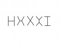
Turn round 90°. And remove all the jumpers to Gnd, without saying.
Difficult to remove jumpers from a photo, but of course no connections to Gnd")
I actually had it turned around 90˚ first as this made more sense to me. However, electrically I cannot see the difference between these and the X (see drawing below)
>And read F5X Preamp Basic Circuit Topology carefully (P.2 of the article).
I guess I should read it better
Turn round 90°. And remove all the jumpers to Gnd, without saying.
Difficult to remove jumpers from a photo, but of course no connections to Gnd
I actually had it turned around 90˚ first as this made more sense to me. However, electrically I cannot see the difference between these and the X (see drawing below)
>And read F5X Preamp Basic Circuit Topology carefully (P.2 of the article).
I guess I should read it better
Attachments
>The one we proposed is available from DK or Mouser, not ?
Yes you did, but as I am about to place a Digikey order I was just probing Davide.
I just realized that heinz1 (in his unofficial BOM) had actually found them (or similar) on Digikey:
50R 6A 570-1109-ND
75R 4A 570-1011-ND
I guess I will take one of each and decide later which to use
One of the thermistors originally suggested by Patrick (Ametherm MS32 50006L) is not available at DK.
MS32 50006 is a non-stock item; minimum order 25: 570-1020-ND
That's why I proposed AS32 50006: 570-1109-ND
MS32 50006 is a non-stock item; minimum order 25: 570-1020-ND
That's why I proposed AS32 50006: 570-1109-ND
Last edited:
In the BOM for the power supply, it was listed per channel:
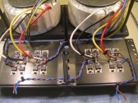
D8-D11, - 4 Diode, - 20A Ultra Fast, - STMicroelectronics, - STTH2002D, -
497-5276-5-ND
1) I see 16 nos here and I only have 8 from the GB.
2) Why wasn't a board done for these instead of hand wiring them?
3) It's difficult to see which wire goes into which leg of the diodes. Could Nic be kind enough to sketch out a diagram?
Thanks.
> 1) I see 16 nos here and I only have 8 from the GB.
There was an error in the BOM and ashaw did not notice it. Therefore you are missing 8 diodes. You have only paid for the 8 you have.
> 3) It's difficult to see which wire goes into which leg of the diodes. Could Nic be kind enough to sketch out a diagram?
See attachment.
There was an error in the BOM and ashaw did not notice it. Therefore you are missing 8 diodes. You have only paid for the 8 you have.
> 3) It's difficult to see which wire goes into which leg of the diodes. Could Nic be kind enough to sketch out a diagram?
See attachment.
Attachments
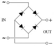
3) It's difficult to see which wire goes into which leg of the diodes. Could Nic be kind enough to sketch out a diagram?
There are also some drawings in the .pdf file compiled by Mark Lai called "Xen Audio F5X Amplifier Case Assembly Notes" which was sent to case subscribers.
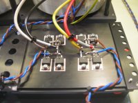
Just a few pics before I close it up.
Thanks for the progress photos.
I'm still a bit surprised that a little rectifier board wasn't part of the project, considering all the attention paid to the other details of the amp. In the end its not that important, but it certainly would clean up things a bit under the PS heatsink.
At the time we did this years ago, there was no rectifier board. I used P2P myself.
Also it has been a DIY project, with a lot of your own participation, and not a finished commercial product from me.
Anyway, there is one (PCB) now.
If you want to get organised, WK will get them made and send to the distributors, as before.
You can do direct paypal this time for the small sum.
But don't ask him to send to 30 addresses.
He has already way too much work ....
OK ?
Patrick
Thanks Patrick. By no means was I being critical at all. I was just stating my surprise considering the amazing amount of attention to detail you have put into the project as a whole.
For those who are interested, I started Rectifier Board GB interest thread here.
For those who are interested, I started Rectifier Board GB interest thread here.
- Home
- Amplifiers
- Pass Labs
- F5X -- the EUVL Approach - The Build Thread