Can anyone tell me the spacing for the diodes on the heatsink?
After discovering the quasimodo thread I am looking to snub the transformers as well as replacing the diodes. Pre-building the bridges (PTP) would reduce the time the amp is out of commission. Anyone snub the primrose tx with the quasimodo?
which diodes you plan to use - FFPF30, HexFreds or else
which diodes you plan to use - FFPF30, HexFreds or else
This one: STTH15S12
Attachments
Transformer Integration
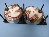
When I was searching in this thread for a nice solution on how to integrate the power transformers and how to solve the transformer connectivity mess I saw that I was not the only one who was on the search for proper solution.
For those how might be interested this the solution I ended up with.
Since I know this question will come:
I have 12 V and 3 V secondary coils such that I can combine them to 9, 12 and 15V. The shown configuration privides 15V each.
Markus
Attachments
")
Transformer Integration
Hi Pmchoong,
the white pieces are flanges made from plastics, more precisely from POM (PolyOxyMethylen). The flanges are sitting on the potting material the center holes of the toroids are filled up with. On the bottom side the transformers are sitting on support rings that are also interfacing to the potting material. The coil itself is free from any mechanical contact and related mouning stress, only the potting material experieces the monting stress.
I attached the sketches of both parts.
Cheers
Markus
Attachments
thank you for reply
please tell us Impression after change
one thing that I remember from Mark posts Is that super fast switching diodes not always guarantee better sound
did you notice relatively high voltage drop - 1.9 V
Yeah, I noticed the large Vf, so I may need to adjust the zener ref. Thankfully I used sockets for those so no big deal to change them. It also has a Softness=2, although with the snubbing not as much of a factor. More importantly, in listening tests (DAC power supply) I preferred it over previous favorites.
I will report the snubber values I find with the quasimodo here, although I'm not sure when that will be (sometimes these projects sit around for months before I get to them).

I would like to use Hifi 2000 case Including 2 x 200 mm heatsinks per side
https://www.modushop.biz/site/index.php?route=product/product&path=66_97_107&product_id=218
what do you think about alternative placement of parts In order to get better heat transfer - pcb Is mounted between two heatsink and all devices are placed at one row using extension wires from pcb
https://www.modushop.biz/site/index.php?route=product/product&path=66_97_107&product_id=218
what do you think about alternative placement of parts In order to get better heat transfer - pcb Is mounted between two heatsink and all devices are placed at one row using extension wires from pcb
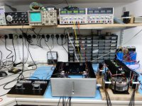
Considering a bigger housing and bigger heat sinks is certainly not a bad idea. The first for ease of integration and extendability and the second for lower operational temperature.
If you could fit besides the amp boards also the associated rectifiers and regulators to outer heat sinks then integration and testing will become much easier since you have everything needed to operate one channel besides the transformer mounted to one heat sink. Hence you could do all the wiring and pre-integration tests outside.
I will continue my bottle ship hobby with the original housing ...
First listening test were not to too bad BTW.
Cheers
Markus
Attachments
Last edited:
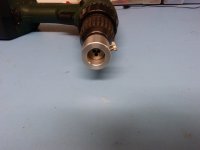
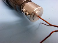
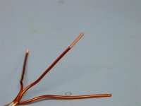
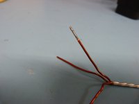
Stripping off enamel insulation from trafo wires
Since we had to shorten the transformator secondary wires we had to strip off the enamel insulation but this turned out to be a very time consuming task ( I have 2 amp units, 2 transformers each, 4 secondaries each, 3 wires each, 2 ends each = 96 wire ends) and the results were also not always of the desired quality. If there are residuals of enamel which are hard to see with bare eyes the solder does not wet properly.
I looked around for appropriate tools but the professional tools with a motorized rotating blade cost more than 500€.
So I invented my own simple and cheap tool. The idea is to cut a thread on the copper wire and herewith to remove the enamel. I use a M1.6 die for stripping off a wire with 1.55mm diameter. This works perfect, one wire is stripped off within less than half a minute and the solder wetting test show very good results.
Cheers
Markus
Attachments
1511120 KNIPEX - Abisolierer | TME Germany GmbH - Electronic components
9 Euros, made in Germany. Available also from Buerklin.
I know German are used to large houses.
You can always put the entire PSU external.
Gets rid of Tx tray fields, leaves you plenty of space inside the amp.
Patrick
9 Euros, made in Germany. Available also from Buerklin.
I know German are used to large houses.
You can always put the entire PSU external.
Gets rid of Tx tray fields, leaves you plenty of space inside the amp.
Patrick
The approach for case design for a Class A power amplifier has been described in full detail in my article at Linear Audio, using the F5X as an example.
I have an arrangement with Jan Didden to make it available for free download.
You may wish to use that as a reference for your own build.
Patrick
I have an arrangement with Jan Didden to make it available for free download.
You may wish to use that as a reference for your own build.
Patrick
- Home
- Amplifiers
- Pass Labs
- F5X -- the EUVL Approach - The Build Thread