
Carlos,
Think about what I asked you a couple of days ago.
Patrick
...done quite a lot of work on that Patrick, it's looking good so far.
Attached two pictures:
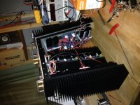
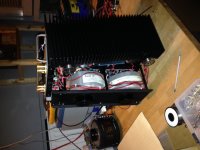
The problem is the following. I do not have screw contacts on the cap boards, as my caps were too big. So I had to hard wire the caps boards to the rectifier. This makes hard to extract the PSU from the rest. So I thought I could manage to wire everything and make the mechanical assembly later, but it does not seem possible.
Specifically, to attach the rear panel to the heatsinks there are three screws on each side. the central one is behind the relay. If you assemble the heatsinks and the rear and front panel, how are you going to connect the wires of the main for the transformers ?
I thought I was close to completion, but I fear that I will need to disassemble it again and try another approach. Please let me know how you did, I am pretty depress :-(
Thanks,
Davide
P.S.: I will ship the heatsinks today.
Attachments
Davide,
I understand your problem. With the transformer cradle in place there is not room enough to access front and back panel mounting screws (or any other mounting screws for that sake).
Therefore the cradle is the last to go in, and only when everything else is assembled/tested (see also Horio's excellent chassis mounting guide). This is actually a nice feature of the amp and the operation is made fairly easy by the screw terminals on the cap boards.... - which you don't have
You should however also be able to disconnect the cap boards from the cradle using the screw terminals on the regulator PCB.
It is likely that you will need to remove the cradle a few times to access amp and control boards so I would recommend that you keep this operation as simple as possible.
Keep up the good work.
Cheers,
Nic
There are two connections that are hard wired between the cradle and the rest:
The main for the transformers
The bridge to first cap connection.
So I guess the only way out for me is to figure out some connectors to attach to the cables to try to overcome the lack of the screw contact on the cap boards.
Nic, the rear panel has the central screw that is covered by the relay. How did you install relay-screw=wire etc ?
Thanks,
Davide
SQ with and w/o speaker relays
As reported in my post
we first build a proto without protection board and we where very satisfied and happy with the SQ. After pre-testing of the protection board we stepwise integrated the protection board and the related relays.
As far as functionality is concerned everyting works as expected but in the first listening tests I had the impression that the SQ has suffered tiny bit. The SQ was still excellent but it appeared to me it was not as clear as before. Also the other team members confirmed my observation in the last Monday´s listening session.
So I am wondering if other F5X DIYers were already brave enough to do a listenting test with and without speaker protection relays and if they could confirm our findings.
Markus
As reported in my post
F5X proto II, first living room test
Markus & The Ulm 5FX Build Team
we first build a proto without protection board and we where very satisfied and happy with the SQ. After pre-testing of the protection board we stepwise integrated the protection board and the related relays.
Our first protection board is now fully integrated in our F5X proto II.
Markus
As far as functionality is concerned everyting works as expected but in the first listening tests I had the impression that the SQ has suffered tiny bit. The SQ was still excellent but it appeared to me it was not as clear as before. Also the other team members confirmed my observation in the last Monday´s listening session.
So I am wondering if other F5X DIYers were already brave enough to do a listenting test with and without speaker protection relays and if they could confirm our findings.
Markus
Davide,
You can try to assembly the whole case first without any electronics and the Back Panel.
Then install the aux. PS, power switch etc. on the Back plate. Then you can install the caps on the 2 sides.....
The last to install is the cradle assembly after fully test.
Mark
You can try to assembly the whole case first without any electronics and the Back Panel.
Then install the aux. PS, power switch etc. on the Back plate. Then you can install the caps on the 2 sides.....
The last to install is the cradle assembly after fully test.
Mark
- Home
- Amplifiers
- Pass Labs
- F5X -- the EUVL Approach - The Build Thread