This is what I have found on the speaker relay but no specs on them.
Here is a reference for these:
http://www.diyaudio.com/forums/pass-labs/209678-f5x-case-3.html#post2966912
I finally have time to check through all the information posted in #452 and #453 and found many interpretations incorrect, especially those related to jumper control.
I therefore suggest that you ignore those two post, until I find time to do a proper write-up.
This will be posted only in the XEN Audio website, so that we retain full editing control.
Until then, I hope you can all learn to have some patience as mis-information is not really of any help to anyone.
Sorry, Nic,
Patrick
Until then, I hope you can all learn to have some patience as mis-information is not really of any help to anyone.
Sorry, Nic,
Patrick
Thank you very much Patrick.
Please substantiate your accusations of mis-information here and not on your private forum. That would favor your credibility.
Since you ask for it :
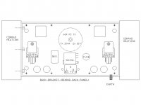
Re Post #453, the Mains Relay should be connected to MR and NOT LSP1 as indicated.
It is designed to be only controlled by SUD and TRIP, and not by CB1 & CB2 (as on the PCB).
Even if you only have CRC, the main transformer should still be wired to MR.
If you want to switch the amp off, then just push button till OFF state, then switch off at the back.
CB1 stands for Control Bit 1, and is equivalent to the standby state.
CB2 is Control Bit 2, and corresponds to the ON or Operate State.
I do not see the wisdom of using the standby state to switch on the mains transformer.
The standby state is for a different purpose, at least according to the original design.
RSR1&2 may not be effective right now as most of the Batch1 people do not yet have regulators.
But Batch 2 would have, and hence they need to wire them.
As to Post #452, there are very good reasons to have a standby state and hence CB1 & CB2 separately.
The regulator shunt relay should be connected to CB1, so that you can warm up the amplifier with the inputs muted and speaker unconnected.
And for each relay, either CB1 is ON and CB2 is OFF, or vice versa, but not both ON.
The terminology ON & OFF is perhaps unfortunate.
It merely means logically effective or ineffective.
For the logic ICs to work properly, you cannot leave them unconnected.
So if you want a particular relay to be ineffective to a certain control signal, you should jumper to the off state.
The fact that the logic circuit is tolerant of both CB1 & CB2 being wired as ON does not make it logically correct.
Of course we provide all flexibilities in the protection board so that you are free to wire whatever relay to whatever control lines as you wish.
Your free choice, but perhaps people want to understand the default recommendation first before making that choice.
In theory one can wire LSP1 & LSP2 in parallel, but I do not see any advantage in doing so.
As you need to connect the Sense lines from both amps any how, and they have to be separate, I myself would stick to Alexis's layout.
But all of these will be described in the publication later in detail.
And my creditability is always here in the open, for ALL to see.
Patrick
Last edited:
Nic,
You have done an excellent job, being the first guy out of the gate. We are all learning and sometimes somebody has to stick his neck out. I for one, appreciate it. It is a big project and a lot to pull together. I have enjoyed the thread and continue to learn a lot.
You have done an excellent job, being the first guy out of the gate. We are all learning and sometimes somebody has to stick his neck out. I for one, appreciate it. It is a big project and a lot to pull together. I have enjoyed the thread and continue to learn a lot.
> Re Post #453, the Mains Relay should be connected to MR and NOT LSP1 as indicated.
It is designed to be only controlled by SUD and TRIP, and not by CB1 & CB2 (as on the PCB).
Even if you only have CRC, the main transformer should still be wired to MR. If you want to switch the amp off, then just push button till OFF state, then switch off at the back.
Wrong. The MR does not go low when the amp is returned to the OFF state. According to you collaborator you designed it this way!
>I do not see the wisdom of using the standby state to switch on the mains transformer. The standby state is for a different purpose, at least according to the original design.
No visdom - just bypassing the flawed function of MR to the benefit of us Batch 1 subscribers")
> RSR1&2 may not be effective right now as most of the Batch1 people do not yet have regulators. But Batch 2 would have, and hence they need to wire them.
And what mis-information did I say about this?
> As to Post #452, there are very good reasons to have a standby state and hence CB1 & CB2 separately. The regulator shunt relay should be connected to CB1, so that you can warm up the amplifier with the inputs muted and speaker unconnected. And for each relay, either CB1 is ON and CB2 is OFF, or vice versa, but not both ON.
Have I said that the SBY state is not useful? Quite the contrary - I say that it is possibly the only useful state to control with jumpers. Read what I write.
> The fact that the logic circuit is tolerant of both being wired as ON does not make it logically correct.
Rather than accusing me of mis-information you should then intervene when your own directions are presented to us wrongly!
> Your free choice, but perhaps people want to understand the default recommendation first before making that choice.
The default recommendations don't work. Don't negate facts.
> And my creditability is always here in the open, for ALL to see.
Thats good to hear
It is designed to be only controlled by SUD and TRIP, and not by CB1 & CB2 (as on the PCB).
Even if you only have CRC, the main transformer should still be wired to MR. If you want to switch the amp off, then just push button till OFF state, then switch off at the back.
Wrong. The MR does not go low when the amp is returned to the OFF state. According to you collaborator you designed it this way!
>I do not see the wisdom of using the standby state to switch on the mains transformer. The standby state is for a different purpose, at least according to the original design.
No visdom - just bypassing the flawed function of MR to the benefit of us Batch 1 subscribers
> RSR1&2 may not be effective right now as most of the Batch1 people do not yet have regulators. But Batch 2 would have, and hence they need to wire them.
And what mis-information did I say about this?
> As to Post #452, there are very good reasons to have a standby state and hence CB1 & CB2 separately. The regulator shunt relay should be connected to CB1, so that you can warm up the amplifier with the inputs muted and speaker unconnected. And for each relay, either CB1 is ON and CB2 is OFF, or vice versa, but not both ON.
Have I said that the SBY state is not useful? Quite the contrary - I say that it is possibly the only useful state to control with jumpers. Read what I write.
> The fact that the logic circuit is tolerant of both being wired as ON does not make it logically correct.
Rather than accusing me of mis-information you should then intervene when your own directions are presented to us wrongly!
> Your free choice, but perhaps people want to understand the default recommendation first before making that choice.
The default recommendations don't work. Don't negate facts.
> And my creditability is always here in the open, for ALL to see.
Thats good to hear
Nic,
You have done an excellent job, being the first guy out of the gate. We are all learning and sometimes somebody has to stick his neck out. I for one, appreciate it. It is a big project and a lot to pull together. I have enjoyed the thread and continue to learn a lot.
Thanks buzzforb,
I have spend a lot of time and money on polishing this turd, but when the designer negate facts I check out
The amp sound fantastic though
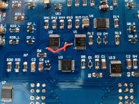
For the sake of information here are the instructions for fixing the start up sequence that ashaw provided: "This should show you how to fix the error, scratch the soldermask away where the red area is and solder together. Cut the traces where there are broken traces and then connect from the via to the other side as marked".
The fix is a bit delicate, but worked right away for me.
I'm sure that Patrick will publish a better way to do this fix so you might want to wait for his directions.
The fix is a bit delicate, but worked right away for me.
I'm sure that Patrick will publish a better way to do this fix so you might want to wait for his directions.
Attachments
Let's all go back to some constructive discussions.
A Batch 2 subscriber who is also a friend did me a great favour to build up his protection board and tested the diff pair (DC detection circuit).
Thank you Markus.
He has similar observations to Nic, that applying a 2V DC did not trigger the TRIP signal, as the output was at 3.6V, and the threshold set at 4V.
A subsequent email discussion confirmed that Alexis's own prototype triggered without problems at 2V DC.
We contribute the different behaviour due to Vgs and Yfs variations in the MOSFETs used,
whereas the 2SJ109BLs I used in my very original circuit 10 years ago has much less variations.
But I am sure you all do not wish me to specify 2SJ109BLs for the protection board.
We know how to fix this, and will publish this later at XEN Audio website, i.e. not here.
The layout problem mentioned in post #469 and elsewhere is a schematics error that both Alexis and I did not spot.
This was not in my original schematics in dwg format.
When we publish the correction later, you will see how easy this mistake be made.
Alexis already proposed a fix as posted in #469.
We shall see if there are simpler ways possible.
Since this is the only mistake we can find, and it can be fixed, we do not consider it necessary to get new PCBs made.
But if you absolutely want perfect boards, we are willing to supply at half price, postage inclusive to local distributors.
This applies to all batch 1 subscribers.
The fix for the diff pair (6 resistors in total) will be 100% at our costs,
though it is a manufacturing variation problem and not a PCB layout or design one.
The circuit description will also be published within the next few days after it has been reviewed by multiple persons.
This will be followed, as I was promised, by build and test instructions from Alexis.
As far as I am concerned, there are no major issues with the protection board.
Just typical Beta-test issues which can be resolved easily by those skilled in the art.
I hope I have now resolved this to your satisfaction, or at least in the process of doing so.
Now I can go back to looking after my family, as I have been for the last two weeks.
Sincerely,
Patrick
Last edited:
Let's all go back to some constructive discussions.
Markus,
do you also confirm my finding that MR remain high when the amp is cycled back to the off state?
Cheers,
Nic
Nic,
I am sorry, I am not so far yet.
We (a group of DIYers) just started with soldering the diff amp sections and we wanted to make sure that this works correctly before we would go ahead with the comperator, logics and supply sections.
It was my pleasure doing some testing for Patrick but I shall leave it up to him to summarize the outcome of the investigations in the circuit description he already announced.
Regards
Markus
The test results from Markus agreed perfectly with the Spice model that I sent Nic a week ago, with recommendations to change a few resistor values.
These resistor values were used by Markus, and his test confirmed that those are correct.
So in the next week or so, Alexis will publish a revision of the schematics plus all other details.
As already mentioned, we shall send replacement resistors to all Batch 1 subscribers in ordinary envelopes in a couple of weeks.
WK is extremely busy with work, and ordering resistors, packing and posting still takes time.
Thank you for your patience,
Patrick
Thank you for the updates Markus and Patrick,
I did indeed get a spice model (that I don't know what to do with.....) and resistor values from Patrick and I understand how to address the diff amp gain/bias issue. Unfortunately, even getting the right voltage over the comparator does not trip any logic downstream.
Just like the rest of what I have found, I think this must be just another soldering flaw of mine
I have decided to give up with the protection board for the moment as this only seems to bring headaches to everybody - and me the most. I will leave to the pro's to solve the issues. For the moment my patched version works perfectly to control the power of the amp.
This weekend I have been listening carefully and trimming the bias of the amp. And THIS IS REWARDING
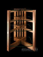
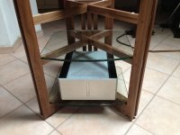
I think I found the right equipment rack for the XEN F5X series
Attachments
- Home
- Amplifiers
- Pass Labs
- F5X -- the EUVL Approach - The Build Thread