Rough, thumbnail calc is 2x 16Ga. ...
O.K. But, die hard?
I test Intel style processor supplies all day long. Ussually 1.2Vout/Vin, whatever. I have at least 10, 24", 10Ga. wires on the + side from the Demo board to the load. I have 10 more 12" wires to a .1mohm shunt and 10 more down to the - side of the output load. The load Saturates at about .55V. This means when the supply is outputting 200+A (Server Apps), I can get to about .65V drop min on the wire! and I'm done! I could take the load out of the loop and the wire would be enough!
I have read, although our pics don't support it, of something like that from the OS boards to the speaker connector of the X600 and X1000...
Personally, I'm not using any of the spec'd little terminal boards on my F5X supply(500VA xfrmr with 66kuF-.1ohm-66kuF CRC).
If I've learned anything from all this, Your conection point might be bundled and crowded but, all those inches of wire have more R than you think, and don't want!
Last edited:
There are 4 poles in the terminal blocks. So 2 positive and 2 negative.
I would use all 4 of them, so each supply line get two wires in parallel.
You may even consider using HF litze for them (individual strands of fine insulated wires in parallel).
But actually it is all academic.
As long as you remain within Class A, a balanced Class A amplifier draws essentially constant current irrespective of signal amplitude.
So no such worries as found in Class AB circuits.
Patrick
Here is a connection set that is equivalent to EUVL's original Schematics.
LSP1/LSP2/ISR1/ISR2:
OFF - ON
SBY - OFF
SUD - ON
TRP - ON
RSR1/RSR2:
OFF - OFF
SBY - ON
SUD - ON
TRP - ON
Attached is a connection diagram put wire straps where the red lines are.
Is the diagram you attached correct?
LSP1/LSP2/ISR1/ISR2:
OFF - ON (I see OFF in the diagram for ISR1)
SBY - OFF
SUD - ON
TRP - ON
RSR1/RSR2:
OFF - OFF (I see ON in the diagram for RSR1 and RSR2)
SBY - ON (I see OFF in the diagram for RSR1 and RSR2)
SUD - ON
TRP - ON
......or maybe I am just getting blind
I would use 1.5mm2 minimum.
Of course for the real die-hard, you can drill out the PCB hole and direct solder.
You lose ease of maintenance and modularity though.
If anything, the connection from the last cap of CRC or CRegC (next) to the amp board is most important.
So keep them short also.
Patrick
why connection got to be thick and short
what would be difference between 1.5mm2 and 0.5mm2
seriously or just posting without thinking
>why connection got to be thick and short
because conductivity is directly proportional to crossectional area and inversely proportional to cable length
>what would be difference between 1.5mm2 and 0.5mm2
9.03 times higher conductivity if you do your math
>why connection got to be thick and short
because conductivity is directly proportional to crossectional area and inversely proportional to cable length
>what would be difference between 1.5mm2 and 0.5mm2
9.03 times higher conductivity if you do your math
3times as much resistance by using 0.5mm² instead of 1.5mm²
Does that mean the resistance would increase from 5milliohms (0r005) to 15milliohms (0r015)?
And it he used 2.5mm², the hypothetical resistance would decrease to 3milliohms (0r003).
What changes in performance would be evident in using those three different wire sizes?
Does that mean the resistance would increase from 5milliohms (0r005) to 15milliohms (0r015)?
And it he used 2.5mm², the hypothetical resistance would decrease to 3milliohms (0r003).
What changes in performance would be evident in using those three different wire sizes?
I think if we want to discuss measureable differences, there will probably be none.
Nevertheless, with a high bandwidth amp like the F5X, I do want to have a low impedance between the PSU caps and the amp itself.
And probably inductance is more important than resistance.
Since Nic has his amp working, and can drive it with a functions generator to say 1MHz,
why not do a "scienfitic study" by first mesurements using enamel wires from 0.1mm2 single wire,
then increase the number of strands to say 20 (20mm2) and see whether you see any measurable differences.
And perhaps followed by a listening test to compare 0.1mm2 and 2mm2 ??
Patrick
I guess it also depends on all the other R that there is in series (PCB traces, cap and mosfet legs etc.). Having cabling much "thicker" than these R's probably makes little sense.
I have enough "scientific studies" at work, so no real interest in measuring cables at home. Also I have already decided what I will use.
I may be able to give the amp a listen tomorrow
I have enough "scientific studies" at work, so no real interest in measuring cables at home. Also I have already decided what I will use.
I may be able to give the amp a listen tomorrow
Looks good.
One of the things that please me most with this project, despite all the trouble, is how many of you has taken the trouble to learn to build amplifiers properly.
Hopefully that will be the first of many years when you can really enjoy this fastinating hobby.
Patrick
One of the things that please me most with this project, despite all the trouble, is how many of you has taken the trouble to learn to build amplifiers properly.
Hopefully that will be the first of many years when you can really enjoy this fastinating hobby.
Patrick
Degen resistors and mute board
Hi,
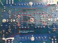
Please take a look at the images 'Degen resistors' and 'Mute connection'.
On the 'Degen Resistor Image' :
1) Is the regen resitors solder onto these pads?
2)Are the jumpers position for the Q11A, Q14A, Q10A and Q7A correct?
3) Is it okay if I didn't remove the tefron sleeve for the jumpers between Q6 and Q15?
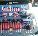
On the 'Mute Connection Image':
4)Does the last hole on the Mute board extend all the way to the amp board or is just extended to the Input board only?
5) The holes right after R103 and R104, where do these goes to?
Thanks in advance.
PMChoong
Hi,
Please take a look at the images 'Degen resistors' and 'Mute connection'.
On the 'Degen Resistor Image' :
1) Is the regen resitors solder onto these pads?
2)Are the jumpers position for the Q11A, Q14A, Q10A and Q7A correct?
3) Is it okay if I didn't remove the tefron sleeve for the jumpers between Q6 and Q15?
On the 'Mute Connection Image':
4)Does the last hole on the Mute board extend all the way to the amp board or is just extended to the Input board only?
5) The holes right after R103 and R104, where do these goes to?
Thanks in advance.
PMChoong
Attachments
Last edited:
>On the 'Degen Resistor Image' :
1) Is the regen resitors solder onto these pads?
2)Are the jumpers position for the Q11A, Q14A, Q10A and Q7A correct?
3) Is it okay if I didn't remove the tefron sleeve for the jumpers between Q6 and Q15?
Yes, yes and yes.
>On the 'Mute Connection Image':
4)Does the last hole on the Mute board extend all the way to the amp board or is just extended to the Input board only?
5) The holes right after R103 and R104, where do these goes to?
The wire does not go all the way to the amp board.
The two holes are the amp inputs and goes to the XLR sockets.
I would not say so.
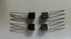
You can have 2SK170BL which have 2.54mm leg spacings (on tape, not in bid).
Mine looks exactly like those on the right.
Only way to find out is curve trace, or measure Idss, then ndegen 5R, 10R, 15R.
And then plot the values to get the curve.
There are enough people with "curve tracers" around.
Patrick
- Home
- Amplifiers
- Pass Labs
- F5X -- the EUVL Approach - The Build Thread