I see you are enjoying yourself.
Patrick
Of course
")
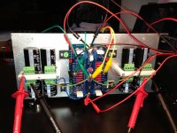
And tonight high-power fun with the PSU and my new-build 4 x 100W 4R dummy load
I may now have to lear to use my PicoScope
Attachments
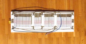
Without the heat-sink my dummy load would exceed the 200˚C rating of the aluminum clad resistors. With the sink I can however handle all 4 supply lines contemporarily and.......
it works a charm!
MS22 75004 thermistor and 3.15A slow-blow fuse. All OK.
5 mV ripple P2P (the scope say 100Hz! Why I thought I was living in a 50Hz country).
Rectification and caps does not generate much heat. The R's in the CRC get very warm, but nothing to worry about.
I have 15V over the load, but I expected a bit more. I hope it is sufficient also for the regulated supplies.
The transformers are not the ones from the GB. I got these from Canterbury windings and they were ordered before Patrick's increased the voltage specification. These have 15V/18A secondaries.
One happy builder
Nic
P.S. what is the easiest way to get traces from the PicoScope software to this forum?
it works a charm!
MS22 75004 thermistor and 3.15A slow-blow fuse. All OK.
5 mV ripple P2P (the scope say 100Hz! Why
I thought I was living in a 50Hz country).Rectification and caps does not generate much heat. The R's in the CRC get very warm, but nothing to worry about.
I have 15V over the load, but I expected a bit more. I hope it is sufficient also for the regulated supplies.
The transformers are not the ones from the GB. I got these from Canterbury windings and they were ordered before Patrick's increased the voltage specification. These have 15V/18A secondaries.
One happy builder
Nic
P.S. what is the easiest way to get traces from the PicoScope software to this forum?
Alexis,
the control PCB is between me and music so I kindly ask for your help in explaining the interface. I do have your schematics, but this is not entirely helpful as there are no pointers towards the amp schematics. To make it easy for you I have below listed the connections I would like you to indicate. Layman terms like "cathode side of left channel speaker relay", would be greatly appreciated. I am sure that several others would appreciate this information. Also a picture of the recommended jumpers for a default F5X would be greatly appreciated.
Cheers,
Nic
PCB left hand side:
LSP1/SENSE1
1: ??
2: ??
3: ??
4: ??
RSR2/ISR2
1: ??
2: ??
3: ??
4: ??
MR/TRP RST
1: ??
2: ??
3: ??
4: ??
PCB right hand side
SENSE2/LSP2
1: ??
2: ??
3: ??
4: ??
ISR1/RSR1
1: ??
2: ??
3: ??
4: ??
> 5 mV ripple P2P (the scope say 100Hz! Why I thought I was living in a 50Hz country).
Draw a rectified waveform and count the ripples.
Or do a simulation with LTSpice.
> Rectification and caps does not generate much heat.
> The R's in the CRC get very warm, but nothing to worry about.
As they should.
> I have 15V over the load, but I expected a bit more.
> I hope it is sufficient also for the regulated supplies.
No real concern.
The regulator still regulates as a cap multiplier even under 16V.
> P.S. what is the easiest way to get traces from the PicoScope software to this forum?
Screen shot.
Patrick
Here is a connection set that is equivalent to EUVL's original Schematics.
LSP1/LSP2/ISR1/ISR2:
OFF - ON
SBY - OFF
SUD - ON
TRP - ON
RSR1/RSR2:
OFF - OFF
SBY - ON
SUD - ON
TRP - ON
Attached is a connection diagram put wire straps where the red lines are.
The connectors that this board is designed to use, if you mant them are 4 way Molex Microblade connectors.
Note:This Board has 24V relay outputs, If you want to use 12V relays as per EUVL for the protection shorts, you must wire them in series off board.
Attachments
Last edited:
the Sense connections go across the amplifier outputs in parallel with the speaker terminals. leave trip reset NC. SENSE1 across one channel and sense2 across the other. (they are the inputs to the DC sense amps ...)
make sure that there is a diode across all relays to stop inductive spikes, these are not on board, and should be at the relay to stop EMI.
make sure that there is a diode across all relays to stop inductive spikes, these are not on board, and should be at the relay to stop EMI.
Last edited:
Also a picture of the recommended jumpers for a default F5X would be greatly appreciated.
The connectors that this board is designed to use, if you mant them are 4 way Molex Microblade connectors.
Alexis, you specified the Molex connectors already in one of your GB BOMs as Digikey WM18981-ND.
But the part Nic was asking for (as I understand) were the jumper headers in the field(s) in which you were placing the red lines in your last .pdf-file. Would a part like this be suitable, or is any breakable single-row 40 pin header with 2,54mm pitch good enough for that purpose?
for the red lines I gust used solid core wire, 0.6mm (the type that you use on a solderless breadboard). however anything that solders and fits in the hole should do, just keep it tidy.
to test I did however use 100mil headers like that, if you use configuration jumpers it makes configuration quite easy.
to test I did however use 100mil headers like that, if you use configuration jumpers it makes configuration quite easy.
I hope AWG16 is sufficient as this is what I'm using
By the way, for one amp 3 m in three different colors will just about do it.
I use stranded teflon sleeved silver/copper (from Alpha Wire) that a local reseller is offering cut to lenth.
By the way, for one amp 3 m in three different colors will just about do it.
I use stranded teflon sleeved silver/copper (from Alpha Wire) that a local reseller is offering cut to lenth.
I would use 1.5mm2 minimum.
Of course for the real die-hard, you can drill out the PCB hole and direct solder.
You lose ease of maintenance and modularity though.
If anything, the connection from the last cap of CRC or CRegC (next) to the amp board is most important.
So keep them short also.
Patrick
Of course for the real die-hard, you can drill out the PCB hole and direct solder.
You lose ease of maintenance and modularity though.
If anything, the connection from the last cap of CRC or CRegC (next) to the amp board is most important.
So keep them short also.
Patrick
- Home
- Amplifiers
- Pass Labs
- F5X -- the EUVL Approach - The Build Thread