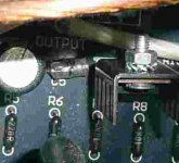
Can you measure the test voltages as per the diagram.
Across R11 you should have between 4 & 5 V this will establish that the CCS is working.
Q1 / Q2 Source to 0V (Power Gnd) should be 4V.
Across R14 should be bewteen 4 & 5V.
If these are OK the active components at the input would seem OK.
If they are OK just replace all the 220uF caps. They are prone to failure in the hot environment of the Aleph.
If that doesnt cure the problem, check all other caps and the feedback loop.
Can you measure the test voltages as per the diagram.
Across R11 you should have between 4 & 5 V this will establish that the CCS is working.
Q1 / Q2 Source to 0V (Power Gnd) should be 4V.
Across R14 should be bewteen 4 & 5V.
If these are OK the active components at the input would seem OK.
If they are OK just replace all the 220uF caps. They are prone to failure in the hot environment of the Aleph.
If that doesnt cure the problem, check all other caps and the feedback loop.
Across R11 I get 5 V.
Q1 / Q2 Source to power ground is 3,65 V
Across R14 I get 4,65 V
Across Q1 there should be approximately 36V D-S
Across Q2 there should be about 40V D-S
Across Q1 I get 48,6 V
Across Q2 I get 53 V
If you read that brief appearance of my diagnosis that I have just deleted - it was wrong.
Next bit is to just replace the three 220uFs C5, C9 and C10.
They're pennies and very difficult to test.
Just use cheapies to prove a point. Once its working you can replace them with exotic parts.
I'll bow to someone with a bit more experience with these amps, I've only got a second hand Aleph 4 that was built by a member of my family.
Try using some rather large 10R resistors in place of the fuses during fault condition testing.
Last edited:
Your output Offset of 12mV would tend to indicate that the DC quiescent condition is stable but everything goes haywire when an AC input is applied.
This, to me, would indicate a capacitor failure or even a joint that has gone bad.
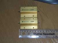
For the 220 uF caps I used Panasonic FC
For the small C8 (10pF) I used this one (styroflex?):
Attachments
Across Q1 I get 48,6 V
Across Q2 I get 53 V
Is this within limits?
I als checked Q3 and I get there 41,3 V between D and S...
I've got some 300W (yes 300Watt) power resistors just for this purpose - a boxful of various values.
We used them at work to fault find a degaussing fit where the amps were outputting 30A in error.
I'll lend you the 2 x 10R if you want to pay the postage.
We used them at work to fault find a degaussing fit where the amps were outputting 30A in error.
I'll lend you the 2 x 10R if you want to pay the postage.
Attachments
Last edited:
Is this within limits?
I als checked Q3 and I get there 41,3 V between D and S...
The input stage appears OK.
You've got 4V to GND where it should be.
If you are itching to carry on fault finding you dont neccessarily need 220uFs to replace the suspect ones. Anything from 100uF to 470uF will prove if this is where the problem lies.
We are not after an amplifier that sounds good at this stage, we are just trying to stop it blowing fuses.
We are not after an amplifier that sounds good at this stage, we are just trying to stop it blowing fuses.
For the 220 uF caps I used Panasonic FC
For the small C8 (10pF) I used this one (styroflex?):
Whatever you used is largely immaterial. Something has failed.
Today, I checked the voltages on the three 220 uF caps.
On C10 I got 325 mV,
on C9 15 Volt,
and on C5 70 mV.
When I made contact with the poles of my DMM on C10 I noticed that some vibration within the amplifier stopped. I thuoght it came from the tranny, but apparently it has to do something with imbalance / oscillation.
It seems that C10 is indeed the culpit!
I will order a new one in the coming days.
Thanks to you all for pointing me in this direction
For the small C8 (10pF) I used this one (styroflex?)
Lucas,
exchange those, and for other types.
Polystyrene capacitors should be soldered with extreme care, when the core reaches 85C they're a goner.
Means that 1 of 3 DIY folks who pick these for a project terminate them during the build-up (2nd one was lucky, 3d got wiser after an earlier mishap)
The styroflex cap is sitting right next to the heatsink of the input IRF9610, the 5-finger does 24-25 C/W thermal resistance.
With a T1 dissipation of +1/2W, that makes more than 12C above ambient temperature inside your Aleph 2 case.
With all the wiring around/above it, slim chance of decent air circulation, the heatsink temperature will likely be above 60C.
A foil cap that handles 85C max, placed next to a +60C heatsink, is what you'd call a sitting duck.
Secondly, if your memory fails you on the cap type (styroflex ?), good chance you picked a junker.
9 out of 10 axial polystyrene caps are garbage, only a handfull good axial types were manufactured in the styroflex era, of which most don't even look like half an inch of transparant hose with a silver wire (aka similar appearance as the 'buisjes' used to fix chronic inner ear infections
 )
) C8 should either be ceramic or mica, better as a cap and more fail-safe.
In Cheesica you also have the luxury to pick PTFE for peanuts, or polypropylene versions, should be possible to squeeZe in between T1 and C4.
Examples :
Paradise Computers en Electronics
Trimmers -hf-electronics
Sometimes go for 50 cents on eplague.
(325mV across C10 implies it's not short circuit. C10 is not there for stability purposes, but to enable dynamic current supply by blocking DC. Did you measure more than 325mV across R21+C10 ? )
Last edited:
- Status
- This old topic is closed. If you want to reopen this topic, contact a moderator using the "Report Post" button.
- Home
- Amplifiers
- Pass Labs
- Problem with one Aleph 2 monoblock