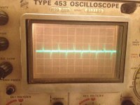
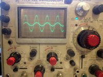
So I bought an O-scope years ago to work on amps and it has been collecting dust. Today I pulled it out and decided to play with it a bit. I don't have a signal generator so I decided to use the 1khz square wave generator that is built into the scope. First I tested the scope itself and it seems to be working fine. Next I tested my aleph 1,7P that I bought off the site and the square seemed close enough to the input for me. The last thing I decided to test was my F5. Now I don't have a large 8ohm resistor so I used a 8ohm tweeter. I know this may not be the best load but it was what I had on hand. Now the amp sounds pretty good to me but I have had a sneaking suspicion that something is wrong somewhere in my system somewhere. I am just not sure if it is my source, preamp or my amp. Attached is what the output of the scope looked like. I had to kind of rig everything up so there may be something throwing everything off right now but I plan to buy some extra cables tomorrow and retest everything. Does this look like a problem with the amp, my setup or something else?
* There is a good chance I am doing something wrong here. I will post more pics tomorrow after I retest.
* There is a good chance I am doing something wrong here. I will post more pics tomorrow after I retest.
Attachments
Now I don't have a large 8ohm resistor so I used a 8ohm tweeter.
Then use whatever high power (3W) resistor you have at hand; a tweeter will not give comparable information due to its large inductance. Also you risc to blow your tweeter as these little fellows are not intended to take significant power.
If you don't have 3 W resistors, parallel 0.25W types and observe the output voltage as to not overload them. For a first toying around, any resistor value will do.
Hannes
Pass DIY Addict
Joined 2000
Paid Member
If you foresee more testing in your future, check out the big green 120w resistors here: Resistors & Pots-MPJA, Inc.
I grabbed 4 of the 16 ohm ones and strung them in parallel with a switch. Two at a time for an 8ohm load and 4 at a time for a 4ohm load. They worked great for testing my Aleph-X amps.
I grabbed 4 of the 16 ohm ones and strung them in parallel with a switch. Two at a time for an 8ohm load and 4 at a time for a 4ohm load. They worked great for testing my Aleph-X amps.
I am new to using a signal generator and and o-scope. What you see above was just me doing things wrong. Its actually very cool that I can now put a signal into an amp and measure what is coming out. I am finally starting to understand how to test a few things. I think DIYaudio needs someone to do a tutorial on how to test all the aspects of an amplifier correctly, for those of us who still have more to learn. I know you can find the information online but it is usually spread accross many different sites and doesn't always deal with the test you may want to use on an amplifier.
I now have some large power reistors, when I get a chance I will hook it up and post a pic.
I now have some large power reistors, when I get a chance I will hook it up and post a pic.
Last edited:
Are you certain that the average DC value of the test pulse is 0V? Routinely
a 0v-+5v sigal is provided and the F5 is DC coupled.

DJNUBZ..... Important point from Mentor Pass, above. Put you scope probes on your scope's 1 KHz output. Make certain your scope is set to DC inputs. Adjust your gain and trace centering so that your squarewave fills your CRT display, with the lower and upper traces of the square wave an equal distance from the center horizontal gractile of your CRT (i.e., the middle horizontal line).
Now, disconnect your scope probe from your scope's 1 KHz input, and connect that probe to ground (at the scope inputs). The resulting trace should lie directly over that center horizontal gractile. THIS MEANS YOU HAVE NO "DC" in your scope's 1 KHz output. (Some scopes will provide a TTL (transistor-transistor logic) 5V square wave, varying from 0 VDC to about 5 VDC). Make certain you are NOT using a TTL signal into your amp--your square wave must be symmetrical on both sides of zero volts.
If you want to get serious about testing, you will want to use an audio generator with variable output frequencies and amplitudes. Either a stand along audio generator (good ones avaiable via surplus stores), or a PC sound-card based unit is good.
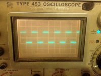
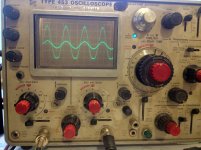
OK so I am getting the hang of it. The square wave pics are using the 1khz calibration on the o-scope. The sine waves are from the eico signal generator I just picked up. The Eico is far from perfect but it's better then nothing. I know I could always use a cd player or computer but I like that I can just twist a dial and see what happens with the signal generator.
All of these were taken with a 4ohm load on the speaker terminals.
1st pic is from my aleph p1.7
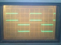
2nd - F5
3rd- F5
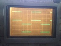
4th - F5 - just starting to clip from what I see. Is this how an F5 should look when it clips?
I zeroed out the DC before all of this.
To me it looks like the F5 handels a square wave better then the aleph P 1.7.
All of these were taken with a 4ohm load on the speaker terminals.
1st pic is from my aleph p1.7
2nd - F5
3rd- F5
4th - F5 - just starting to clip from what I see. Is this how an F5 should look when it clips?
I zeroed out the DC before all of this.
To me it looks like the F5 handels a square wave better then the aleph P 1.7.
Attachments
looks like ur power supply is sagging asymmetrically. You can use the other trace on the scope to check it. That channel should be on DC. You will put the probe on it, and set the vertical gain so that it is nearly at full deflection.
I would manually offset the trace in the opposite direction that it will go (moved down for +, and moved up for -) so that you can use more gain in the vertical amp, and see changes more easily.
Now, with no load, note the position of the trace.
With the other channel on the sine wave, and a load on the amp, bring the level up towards clipping.
Note the position and shape of the trace that is the DC rail voltage. See where it moves when the amp is clipping (if at all) and how much ripple appears (if any).
Do this for both channels.
IF the rail moves the same number of volts AND the ripple that appears looks essentially identical, then the issue is in the offset, bias or gain of 1/2 of the amp channel.
If BOTH channels do the same thing, then report back, and we'll have to consider the situation more carefully.
So, if one rail is drooping more than the other the same way on both channels, AND there is no DC offset at the output, then it is NOT a fault in one channel, or a bad component (unless you did the same mistake, if there is one, on both channels).
Let's see what you get?
_-_-bear
But first, please perform a detailed cleaning of your beautiful old Tektronix oscilloscope.
I used to refurbish and resell a lot of older Tek scopes. You will probably be amazed at how beautiful it will be, if it's well-cleaned! (After that, maybe you could rig a dust-cover for it, at least for extended periods of non-use.)
I used to refurbish and resell a lot of older Tek scopes. You will probably be amazed at how beautiful it will be, if it's well-cleaned! (After that, maybe you could rig a dust-cover for it, at least for extended periods of non-use.)
OK so I tested this out and I think I did it correctly. I did not get any sag on either rail. I am pretty sure I did everything correctly. I did take my probe and put it on R5 and R6 and the wave form is distorting. I am still new to this so tell me if I am doing something wrong. I thought I was testing the output of the jfets, am I right? From all this I am duducing that the signal distorting + the lack of sag means I have a problem with either my jfets or how their gain is set. So what is my next step?
Could it be possible that the signal generator is causing some sort of issue due to output impedance or something else odd? Should I pull out an old cd player and burn a cd with test signals and try that as well or am I worrying to much about nothing?
gootee, what do you recommend I use to clean it? Can I just use all purpose house cleaner or is there something special I should use?
in your 1st photo were the meter probes after the capacitor in the crossover? If so the signal you had was normal, no low frequencies. If you look at a square wave output of a preamp that has tone controls play with the bass and treble controls. You will see that the square wave output changes quite a bit depending on the frequencies being boosted or cut. A square wave is just sine waves. If you change the amplitude or phase of the sine waves the square wave will change. Adjusting the bass and treble controls changes the amplitude and phase of the sine waves that make up the square wave. The flatter the frequency response and the phase response the better the square wave will look.
in your 1st photo were the meter probes after the capacitor in the crossover? If so the signal you had was normal, no low frequencies. If you look at a square wave output of a preamp that has tone controls play with the bass and treble controls. You will see that the square wave output changes quite a bit depending on the frequencies being boosted or cut. A square wave is just sine waves. If you change the amplitude or phase of the sine waves the square wave will change. Adjusting the bass and treble controls changes the amplitude and phase of the sine waves that make up the square wave. The flatter the frequency response and the phase response the better the square wave will look.
It was hooked to a fostex ft17h tweeter. I realize now that was not a good plan for a load. I am not as worried about that now, as I am the clipped response I am getting from sine waves.
gootee, what do you recommend I use to clean it? Can I just use all purpose house cleaner or is there something special I should use?
Yes, you can use something like Formula 409. But don't spray anything on the scope. Spray onto some folded-up paper towels.
A small scrub brush or toothbrush will probably come in handy, as will some cotton swabs.
If you later go on to clean contacts inside, etc, look up DeOxit, from caig.com.
What could be causing my uneven clipping? if it is happening on both channels of my amplifier and, from what I can tell, is happening in the first stage?
I have some deoxit but I am little unsure about poking around inside the scope. It works ok as it is, it's not perfect but I don't want to go in there and mess something up. The biggest problem I run into is that when I try using it in the 5 or 10 mv region the line jumps to a new location and i have to recenter it with the position knob. 10mv is still pretty useable but 5mv isn't. Is there anything I should be sure to check on this unit?
I have some deoxit but I am little unsure about poking around inside the scope. It works ok as it is, it's not perfect but I don't want to go in there and mess something up. The biggest problem I run into is that when I try using it in the 5 or 10 mv region the line jumps to a new location and i have to recenter it with the position knob. 10mv is still pretty useable but 5mv isn't. Is there anything I should be sure to check on this unit?
- Status
- This old topic is closed. If you want to reopen this topic, contact a moderator using the "Report Post" button.
- Home
- Amplifiers
- Pass Labs
- Just starting to learn o-scope, F5 1k square looks funny