Dear Mod Zen
The tantalum capacitors that I have are the new (drop). Have you tried them in the signal path? I already did upgrade cd player with tantalum decoupling in DC, they are fantastic for some applications already made a phono pre with them, they were better Clarity Caps SA and obbligato caps copper, WIMA MK10 and others. It costs nothing to try this application .... Greetings ....
The tantalum capacitors that I have are the new (drop). Have you tried them in the signal path? I already did upgrade cd player with tantalum decoupling in DC, they are fantastic for some applications already made a phono pre with them, they were better Clarity Caps SA and obbligato caps copper, WIMA MK10 and others. It costs nothing to try this application .... Greetings ....
Building my Aleph Mini at the moment. My power supply is running 27.5v rails. Everything looks not bad but my DC offset is around 90mv and I'm running the stock 47k resistor in r13. I read that some people were using the trimpots and soldering the middle leg to an outer leg. I will do this for both R8 and R13 tomorrow.
Any tips would be great thanks


Any tips would be great thanks
ANTEK 300va toroidal with 20vac secondaryswhat's Mini with 27V5 rails?


Mini means lowered rails and Iq , comparing to original
no benefits in highish rails , counting on max dissipation per device in range of 40-50W and your heatsink seemingly being capable of no more than 80-100W per channel anyway
except in case that you intend of driving 16R load , which is pretty much rare nowadays
in short - you're just burning heat ....... take 15Vac secondaries if possible and crank Iq up to 2A , and you're good
Jason Leamers told me to go a 300va with 18v to 20v secondarys and get like 25 to 30wpc.Mini means lowered rails and Iq , comparing to original
no benefits in highish rails , counting on max dissipation per device in range of 40-50W and your heatsink seemingly being capable of no more than 80-100W per channel anyway
except in case that you intend of driving 16R load , which is pretty much rare nowadays
in short - you're just burning heat ....... take 15Vac secondaries if possible and crank Iq up to 2A , and you're good
He offered the boards to me and told me to give it a try.
The heat sinks are pretty decent in size and so far are only like warm. I think his claim was it was like a Aleph 30.

I read the tread and didn't see anyone get near 2a on the bias!OK , fine with me
maybe to change name of your build to (Not so) Mini

:WhoIsThisCampaignerFace:
:stupid:
:nicevoltagedropemoji: 95kv!
... well, that would be me ... 
I see that you use BrianGT boards as well.
My first iteration was "Aleph Mini" (chose to call it "Aleph Single", which is more appropriate), running at 19V and 2.2A bias.
Later rebuilt to "Aleph J Single", running at 19V / 2.2A, later again at 24V / 2.0A (I did like the 19V / 2.2A version better at the time).
I have built on big heatsinks, though - currently, my M2 is installed in that case and using that powersupply.
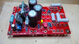
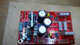
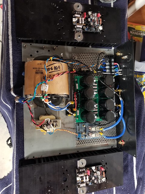
I used pots in all three locations that are labeled "adjust ..." (... DC Offset, ... AC Gain, ... Bias Current) in the attached schematic "Aleph 30 by algar_emi" that is still the standard for all things Aleph 3/30.
You can see the pots in the attached photos - the two gray ones had to be the small variety, Bourns 3266 series or equivalents.
For reference to the parts numbers on the PCB, I have also attached the schematic for BrianGT's implementation ("miniasch") that you and I have. For an "Aleph Single", only the left part of the schematic is relevant; the right part are the extra outputs bords you can use to build an Aleph 30 proper, with triple outputs.
Best regards, Claas
I see that you use BrianGT boards as well.
My first iteration was "Aleph Mini" (chose to call it "Aleph Single", which is more appropriate), running at 19V and 2.2A bias.
Later rebuilt to "Aleph J Single", running at 19V / 2.2A, later again at 24V / 2.0A (I did like the 19V / 2.2A version better at the time).
I have built on big heatsinks, though - currently, my M2 is installed in that case and using that powersupply.
I used pots in all three locations that are labeled "adjust ..." (... DC Offset, ... AC Gain, ... Bias Current) in the attached schematic "Aleph 30 by algar_emi" that is still the standard for all things Aleph 3/30.
You can see the pots in the attached photos - the two gray ones had to be the small variety, Bourns 3266 series or equivalents.
For reference to the parts numbers on the PCB, I have also attached the schematic for BrianGT's implementation ("miniasch") that you and I have. For an "Aleph Single", only the left part of the schematic is relevant; the right part are the extra outputs bords you can use to build an Aleph 30 proper, with triple outputs.
Best regards, Claas
Attachments
I hope @slomatt doesn't object to me using this thread to post my mini Aleph build but this thread was a HUGE help to me figuring it all out given that so many variations exist at this point.
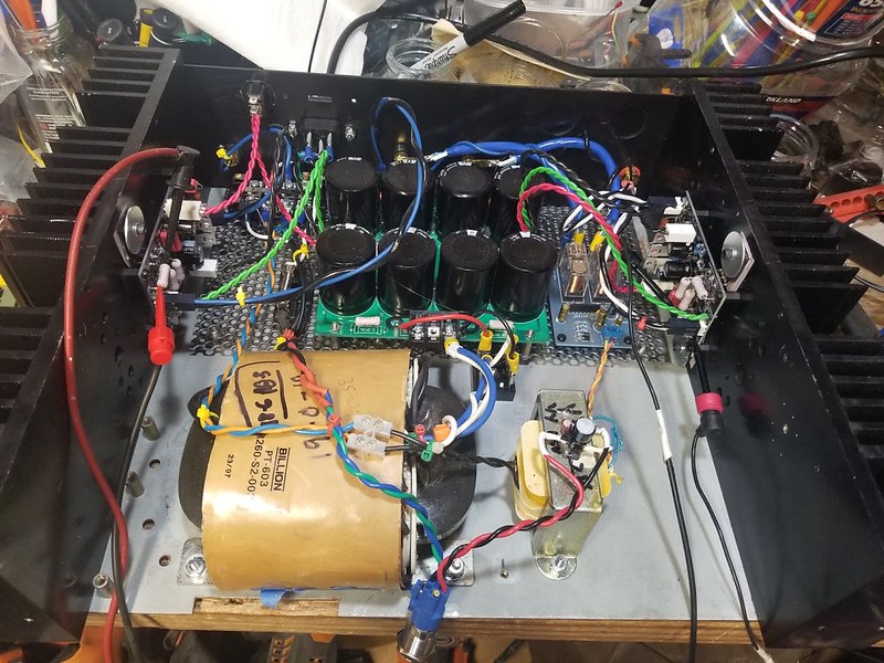
Building the amp
psu
It turned out the transformer that I had labelled 24V in my parts bin was not 12-0-12 but 24-0-24 which put an initial spanner in the works. I had a 35-0-35 transformer in the bin too so I decided to try my hand at unwinding the secondary and clipping it in 1/2 to give me a theoretical 17.5 vAC
I can assure anyone who has this transient mad idea, stop and buy a transformer - winding those secondaries tight and aligned was a major PIA and I ended up with serious repetitive strain injury in my wrists. BUT the project was a success and I ended up with 19-0-19 when measured.
The chassis was a swap meet find - a repurposed Tandberg case that I cleaned up.

back panel

FETs mounted
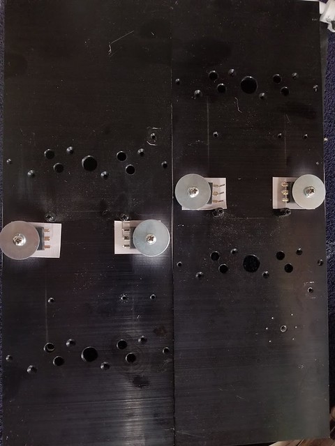

Ready to be tested
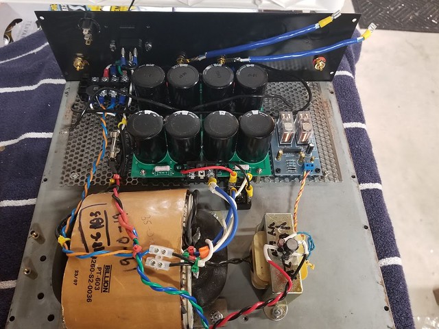
Wiring added

Test phase
- initial bias at stock settings for power up
[url=https://flic.kr/p/2hfGz7Z]
Fully biased to 1.2A
I let it cook for several hours with repeated bias setting until it finally settled in - put it into the bench test system to make sure it generated music and it sounded promising.
Moved it to my desk which is where it will ultimately rest for near field listening while I work at home.
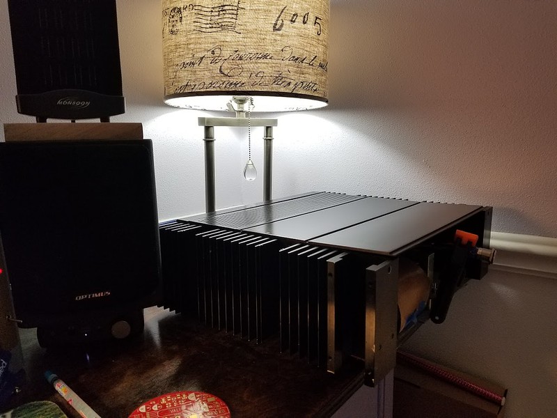
I can pick up a very low level hum in the system which I will address once I figure out the front plate , in the mean time, I will continue to enjoy what appears to be another winning design from NP.
Thanks to all who posted in this forum to guide my ability to stuff an old project and many thanks to @skiroe for offering up his boards in the swapmeet.
AND never enough thanks for the open sharing and continued support of the grand Pappa of DIY
..dB
Building the amp
psu
It turned out the transformer that I had labelled 24V in my parts bin was not 12-0-12 but 24-0-24 which put an initial spanner in the works. I had a 35-0-35 transformer in the bin too so I decided to try my hand at unwinding the secondary and clipping it in 1/2 to give me a theoretical 17.5 vAC
I can assure anyone who has this transient mad idea, stop and buy a transformer - winding those secondaries tight and aligned was a major PIA and I ended up with serious repetitive strain injury in my wrists. BUT the project was a success and I ended up with 19-0-19 when measured.
The chassis was a swap meet find - a repurposed Tandberg case that I cleaned up.
back panel
FETs mounted
Ready to be tested
Wiring added
Test phase
- initial bias at stock settings for power up
[url=https://flic.kr/p/2hfGz7Z]
Fully biased to 1.2A
I let it cook for several hours with repeated bias setting until it finally settled in - put it into the bench test system to make sure it generated music and it sounded promising.
Moved it to my desk which is where it will ultimately rest for near field listening while I work at home.
I can pick up a very low level hum in the system which I will address once I figure out the front plate , in the mean time, I will continue to enjoy what appears to be another winning design from NP.
Thanks to all who posted in this forum to guide my ability to stuff an old project and many thanks to @skiroe for offering up his boards in the swapmeet.
AND never enough thanks for the open sharing and continued support of the grand Pappa of DIY
..dB
Hi Guys,
I need some help :-( I have build a mini but for some reason my speaker output voltage is way off, is at -30 volts! At the lower 240 FET i have a voltage of approx. 5 V source-drain. Current through both 240's is 300mA and controllable with the potmeter.
Where should i start to look?
Tnx !
Frank
I need some help :-( I have build a mini but for some reason my speaker output voltage is way off, is at -30 volts! At the lower 240 FET i have a voltage of approx. 5 V source-drain. Current through both 240's is 300mA and controllable with the potmeter.
Where should i start to look?
Tnx !
Frank
Last edited:
- Status
- This old topic is closed. If you want to reopen this topic, contact a moderator using the "Report Post" button.
- Home
- Amplifiers
- Pass Labs
- Mini Aleph Build