Hi Matt,
Please forgive my ignorance, can you please show me on how you install a multiturn potentiometer in place of R8? As far as I know, they have 3 legs on it, do you use only 2 legs?
As 6L6 posted you just need to solder the wiper to either of the legs.
The way a potentiometer works is that there is a fixed resistance between the two outer pins, and the middle pin is connected to the wiper which moves between the outer legs. For example, if you have a 100 ohm linear pot then you'll measure 100 ohms between the outer legs, and the resistance between the wiper and either leg will vary from 0-100 ohms as you adjust it. This allows you to use the pot as a voltage divider with two resistances that are inversely related. If you short the wiper to one of the legs you'll have a variable resistance between the wiper and the other leg.
In this particular case you just want to find a potentiometer where the outer two legs are spaced properly to fit on the board, and then you bend the wiper (center pin) and solder it to one of the legs.
I used the following parts and they fit just fine.
Bias adjustment (replaces R13)
http://search.digikey.com/scripts/D...ng=en&site=us&keywords=SP064W-200K-ND&x=0&y=0
DC offset adjustment (replaces R8)
http://search.digikey.com/scripts/DkSearch/dksus.dll?vendor=0&keywords=SP064W-500-ND
- Matt
By the way - for those blue pots, I strongly advice you use some solid glue, like silicon when you install it on the board. With some models the pin connections aren't strong enough and after adjusting them a couple of times they might bend and snap out of the blue casing. A dot of hot glue fixes that.
This evening I temporarily put an additional 1.5k ohm resistor in parallel with each existing 1.5k ohm R14 and R16 resistors so I could test how the circuit would behave if those were 750 ohm instead. With this setup I was able to increase the bias to 1.25A before it maxed out. Based on this I am going to leave the stock R14/16 in place and run ~1.2A bias for now. If I need to go higher I will replace the 0.47 ohm source/sense resistors with 0.33 ohm resistors. Assuming the current source can maintain the same voltage range across R28 this should make a 1.5A bias easily attainable.
While I had the boards out of the amp I also bypassed C1/2/3 with 0.01uF 63v Vishay KP18303 capacitors. I haven't had a chance to listen these yet, but hope they make a noticeable improvement.
- Matt
While I had the boards out of the amp I also bypassed C1/2/3 with 0.01uF 63v Vishay KP18303 capacitors. I haven't had a chance to listen these yet, but hope they make a noticeable improvement.
- Matt
Matt, have you checked your amp with a 10Khz square wave? Mine looked quite sub-optimal, and with the assistance of Zen Mod I dialed in the value of C4 (20 pf) and improved the measured performance appreciably.
The gory details start at post 79 in this thread:
http://www.diyaudio.com/forums/pass-labs/209627-aleph-30-best-choice-c1-c2-c3-brian-gt-pcb-2.html
The gory details start at post 79 in this thread:
http://www.diyaudio.com/forums/pass-labs/209627-aleph-30-best-choice-c1-c2-c3-brian-gt-pcb-2.html
Matt, have you checked your amp with a 10Khz square wave? Mine looked quite sub-optimal, and with the assistance of Zen Mod I dialed in the value of C4 (20 pf) and improved the measured performance appreciably.
The gory details start at post 79 in this thread:
http://www.diyaudio.com/forums/pass-labs/209627-aleph-30-best-choice-c1-c2-c3-brian-gt-pcb-2.html
Not yet, but I did see your discussion with Zen Mod a few days ago and it is on my to do list. I have some large 8 ohm resistors on order to use as a dummy load. Thanks for pointing this out!
- Matt
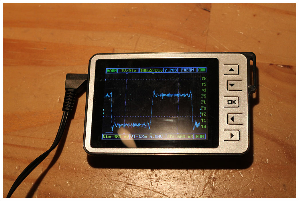
I dug up some 10w 3.3ohm resistors and made a 6.6ohm dummy load to test the amp but quickly ran into a problem. I used a signal generator on my laptop and was unable to get a clean 10kHz square wave using either the built in DAC or an external one, as the frequency increased the waveform on my scope looked more and more like a sine wave instead of a square wave. I checked on both my DSO Nano V2 (200KhZ) and a not-quite-properly-working 35MHz scope and saw the same results on both. So, this makes high frequency testing very difficult.
I was able to test using a 1kHz square wave and had the following results. Due to limitations of the signal generator I was testing at a low voltage. Interestingly the signal directly out of the laptop showed the same noise you see on the amp output shown on the Nano.
First off here is the amp output of a 1khz square wave displayed on the DSO Nano. As you can see there is a lot of noise.
My full-size scope is having issues at the moment, but I was able to get a semi-clear read. This seems to show ringing on the 1kHz signal.
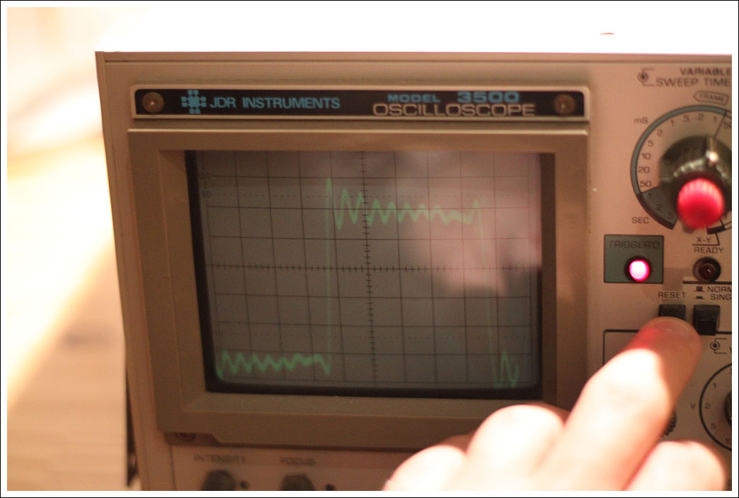
So, based on the last image it does look like more tweaking is in order. Before that I'm going to try to get a better test signal so I can get cleaner measurements.
- Matt
I was able to test using a 1kHz square wave and had the following results. Due to limitations of the signal generator I was testing at a low voltage. Interestingly the signal directly out of the laptop showed the same noise you see on the amp output shown on the Nano.
First off here is the amp output of a 1khz square wave displayed on the DSO Nano. As you can see there is a lot of noise.
My full-size scope is having issues at the moment, but I was able to get a semi-clear read. This seems to show ringing on the 1kHz signal.
So, based on the last image it does look like more tweaking is in order. Before that I'm going to try to get a better test signal so I can get cleaner measurements.
- Matt
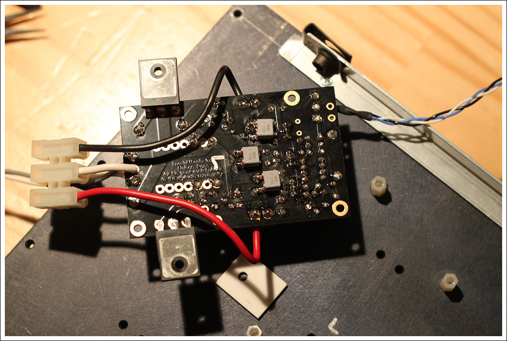
Since I'm blocked from tweaking until I can improve my testing equipment how about some more build pictures? ")
Here are the KP1830 0.01uF 63v bypass caps installed.
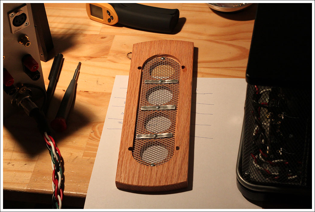
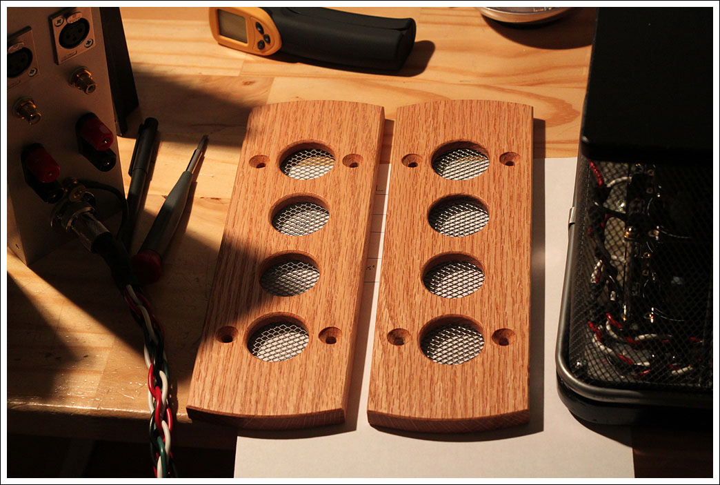
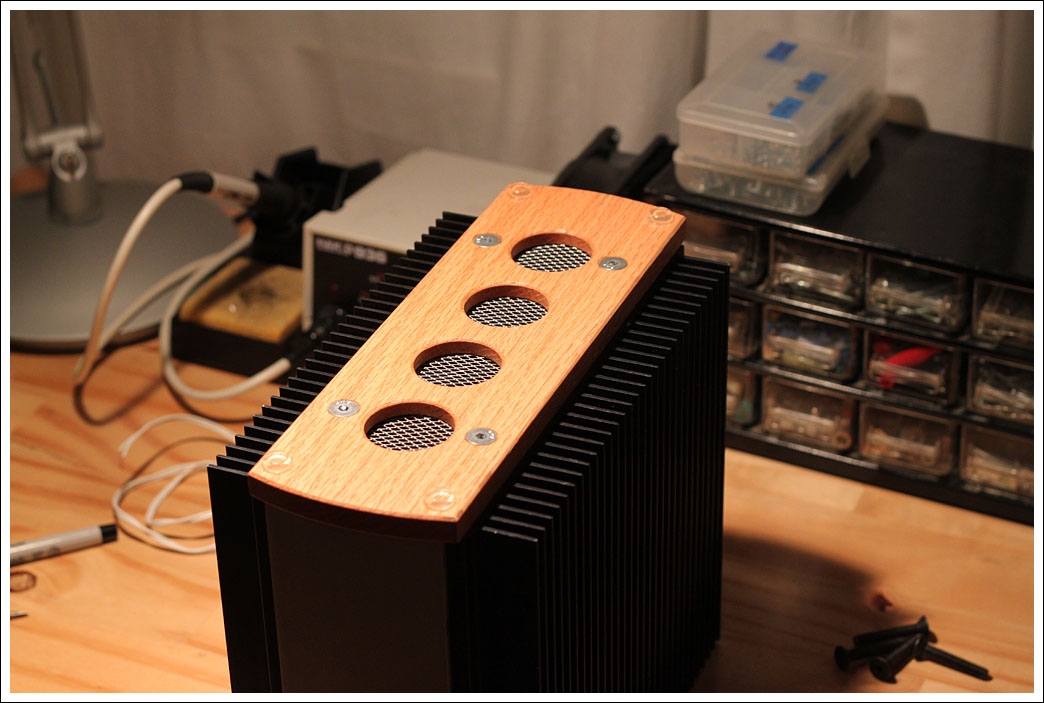
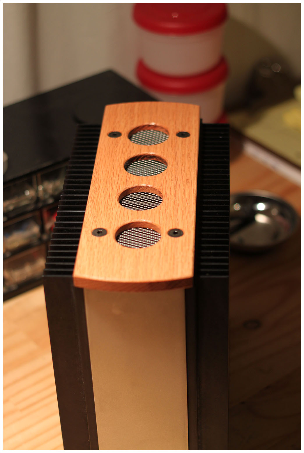
The top and bottom are 1/2" oak with grating from the IKEA garbage can installed to keep fingers out.
The MOSFETS are mounted using aluminum oxide pads and large washers. They are torqued to 7in-lb.
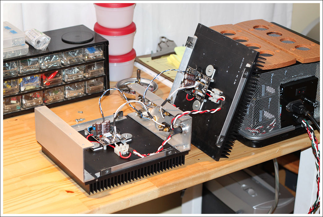
Currently the heatsinks are attached to the front and back panels using "hidden" screws on the inside. These are a major pain to install and I'm going to switch to external fasteners next time I have the amp apart. The two amp boards just barely fit inside.
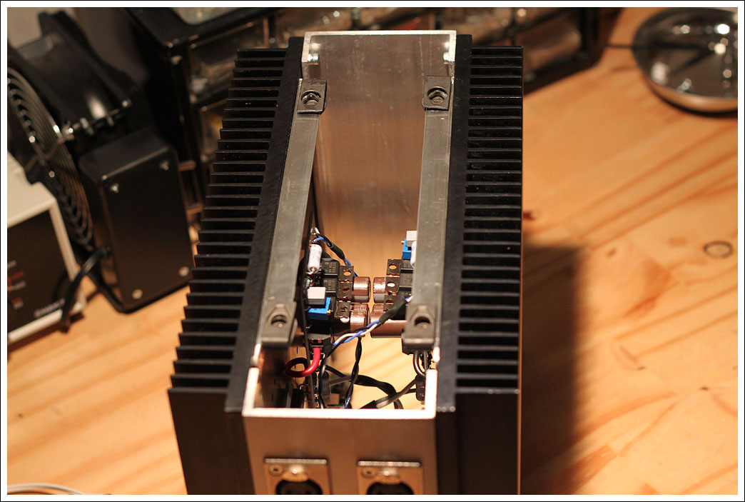
The bottom and top are bolted on using recessed pan head bolts.
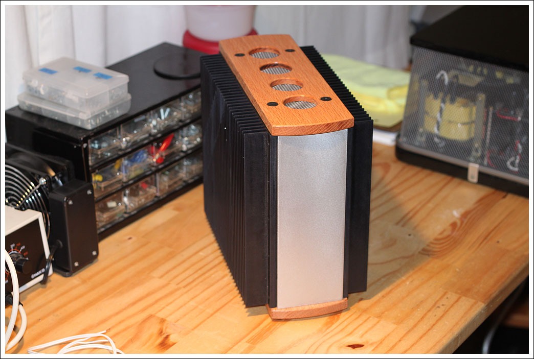
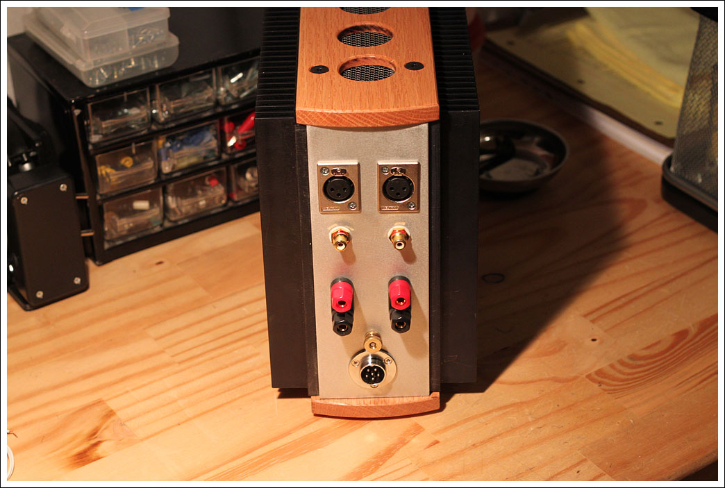
Here's the back panel with the recently added grounding lug.
- Matt
Here are the KP1830 0.01uF 63v bypass caps installed.
The top and bottom are 1/2" oak with grating from the IKEA garbage can installed to keep fingers out.
The MOSFETS are mounted using aluminum oxide pads and large washers. They are torqued to 7in-lb.
Currently the heatsinks are attached to the front and back panels using "hidden" screws on the inside. These are a major pain to install and I'm going to switch to external fasteners next time I have the amp apart. The two amp boards just barely fit inside.
The bottom and top are bolted on using recessed pan head bolts.
Here's the back panel with the recently added grounding lug.
- Matt
Very very pretty. I am quite jealous.
Also a bit worried about how am I ever going to test mine. Once I eventually finish it, of course
Thanks for the kind words.
Looks great! Where did the channel aluminum come from?
Thank you. Variac kindly provided the aluminum channel. You can likely find it locally, or online at McMaster.
McMaster-Carr
- Matt
Pass DIY Addict
Joined 2000
Paid Member
Very very cool!From where the grid come from?
Are you referring to the metal mesh on the power supply casing and the top and bottom of the amps? If so, that is a $2 garbage can from IKEA.
Very nice build, Matt! I've been following your thread since the beginning and I really like the dual-chassis layout. I've seen a few others take this approach and it seems to have a number of interesting advantages.
Thanks for sharing!
Eric
Thanks. Pass recommends placing the power supply 2+ feet from the amp, so I figured I'd put them in separate cases.
- Matt
I finally got my oscilloscope repaired and purchased a function generator that can output a clean 10kHz square wave.
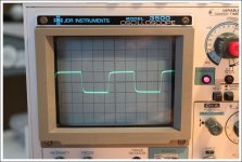
The attached photos show the output of my MiniA (biased at 1.2A) with a 10kHz square wave input signal of varying amplitude. The amplifier was driving a 50w 8ohm resistor. The oscilloscope is set at 2v/div and was recently calibrated so it should be fairly accurate.
Some calculations for future reference:
Vrms = Vp-p / 2.82
P = V^2 / R
R = 8ohm
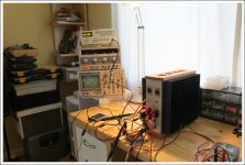
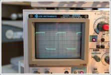
Photo 1: The testing setup in case anyone is interested.
Photo 2: Output at 4Vpp = 1.42Vrms = 0.25w
To my eye this looks pretty clean with no oscillation and just a bit of angle in the ramp up which I believe means a small amount of loss at high frequencies.
Photo 3: Output at 8Vpp = 2.84Vrms = 1w
Looks pretty much the same as 4Vpp.
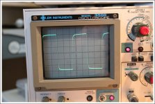
Photo 4: Output at 12Vpp = 4.26Vrms = 2.3w
Here the flat top of the square wave is getting a bit more angled.
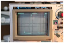
Photo 5: Output at ~15Vpp = 5.32Vrms = 3.5w
Above this level the leading edge of the square wave gets progressively more "bent" and the small overshoot bump appears at the top.
I'm just learning how to evaluate amps based on their output waveforms and would greatly appreciate any help interpreting these results. How much deformation of the square wave is reasonably expected? Does the photo of 15Vpp indicate a major compromise in sound quality, or just some high end roll off? When I have time I plan to go through a similar process with a sine wave to see when clipping starts to occur.
- Matt
The attached photos show the output of my MiniA (biased at 1.2A) with a 10kHz square wave input signal of varying amplitude. The amplifier was driving a 50w 8ohm resistor. The oscilloscope is set at 2v/div and was recently calibrated so it should be fairly accurate.
Some calculations for future reference:
Vrms = Vp-p / 2.82
P = V^2 / R
R = 8ohm
Photo 1: The testing setup in case anyone is interested.
Photo 2: Output at 4Vpp = 1.42Vrms = 0.25w
To my eye this looks pretty clean with no oscillation and just a bit of angle in the ramp up which I believe means a small amount of loss at high frequencies.
Photo 3: Output at 8Vpp = 2.84Vrms = 1w
Looks pretty much the same as 4Vpp.
Photo 4: Output at 12Vpp = 4.26Vrms = 2.3w
Here the flat top of the square wave is getting a bit more angled.
Photo 5: Output at ~15Vpp = 5.32Vrms = 3.5w
Above this level the leading edge of the square wave gets progressively more "bent" and the small overshoot bump appears at the top.
I'm just learning how to evaluate amps based on their output waveforms and would greatly appreciate any help interpreting these results. How much deformation of the square wave is reasonably expected? Does the photo of 15Vpp indicate a major compromise in sound quality, or just some high end roll off? When I have time I plan to go through a similar process with a sine wave to see when clipping starts to occur.
- Matt
Attachments
Matt: That leading edge looks quite good to me....although I forget what the tilt means...LF rolloff??.... as far as the leading edge, that's about what I'm hoping for with a 15pf feedback comp cap (which I'll get with my next Digi-key order). With a 20pf cap, my leading edge is a bit rounder IIRC.
Did you also calibrate your probe with your scope?
Did you also calibrate your probe with your scope?
Last edited:
- Status
- This old topic is closed. If you want to reopen this topic, contact a moderator using the "Report Post" button.
- Home
- Amplifiers
- Pass Labs
- Mini Aleph Build